Structural/Accessory Maintenance
156
Marking System Calibration
1. Visually inspect the recording thermometer
sensing bulb located in the evaporator near the
supply air grille. Make sure it is securely
fastened and clear of debris.
2. Start the unit and adjust the temperature
setpoint to 0 C (32 F). Operate the unit until
the supply air temperature reaches 0 C (32 F).
Enter the Data menu on the controller display
and view the supply air temperature screen.
Press the 5 key two times to lock the screen on
the display for 10 minutes.
3. Wait at least 5 minutes to allow the recording
thermometer sensing bulb temperature to
stabilize. Then compare the supply air
temperature in the controller display with the
recording stylus of the recorder. Write down
both readings.
4. If the average difference is 0.6 C (1.0 F) or
less, do not attempt to recalibrate.
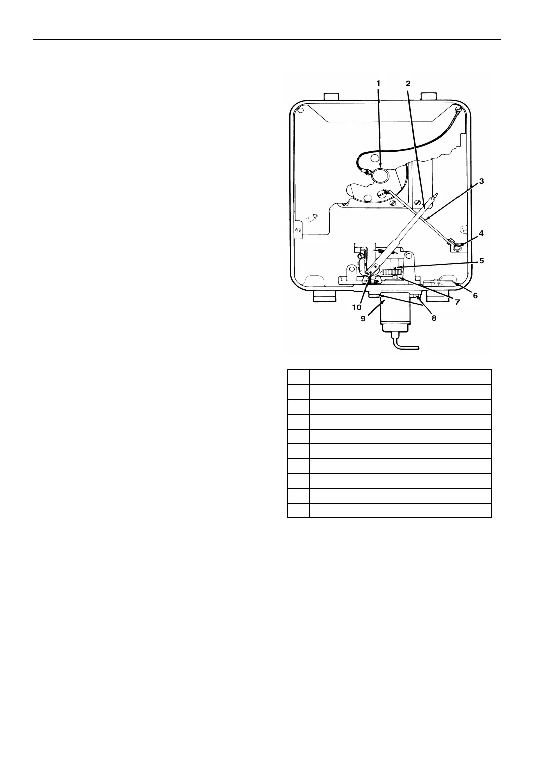
5. If the recorder needs recalibration:
a. Loosen the Allen setscrew (S) using a
small slotted screwdriver.
b. Adjust shaft (J) with a 5 mm (3/16 in.)
open end wrench until the recording stylus
pointer is aligned to the temperature
reading that agrees with the supply air
temperature in the controller display. To
decrease the stylus temperature reading,
turn the shaft to the left (clockwise). To
increase the reading, turn the shaft to the
right (counterclockwise).
c. Tighten Allen setscrew (S).
d. Wait another 5 minutes while the unit
operates on Cool. Verify that the recording
thermometer reading is stable and agrees
with the supply air temperature in the
controller display.
e. Press any key to unlock the controller
display screen.
1. Knurled Knob
2. Recording Stylus
3. Lifter Arm
4. Allen Screw
5. Set Screw “S”
6. Key Mounting Clip
7. Adjustment Shaft “J”
8. Element Flange Screws “D”
9. Thermal Element
10. Stamping
Figure 60: Partlow (SR) Recording Thermometer
AXA0201

 Loading...