7
© 2009 - 2011 TOSHIBA TEC CORPORATION All rights reserved e-STUDIO555/655/755/855
LASER OPTICAL UNIT
7 - 9
7.3 Laser Diode Control Circuit
This equipment uses an AlGaAs type semiconductive laser with 10 mW of optical output power rating.
This laser emits a beam in a single transverse mode in approx. 785 nm wavelength. PIN diode for
monitoring optical output in this laser controls the laser intensity.
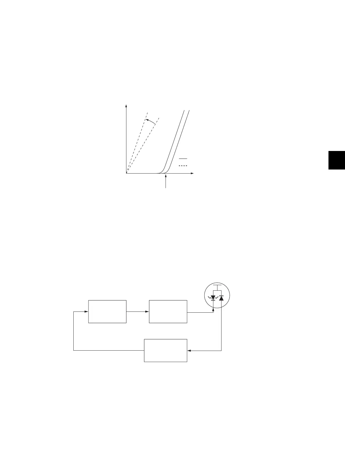
The relation between the forward current and optical output of a semiconductive laser is as shown
below. Beam emission starts when the forward current exceeds a threshold current, and then the laser
outputs a monitor current which is proportionate to the optical output. Since semiconductive lasers have
an individual variability in their threshold current and monitor current, the optical output needs an
adjustment to be maintained at a certain value.
The optical output of a semiconductive laser decreases as the laser temperature rises. Therefore APC
(Auto Power Control) needs to be performed to maintain a constant optical output.
Fig. 7-9
A block diagram of the semiconductive laser control circuit is shown below. The semiconductive laser
performs a monitor efficiency regulation (a process to control a monitor current for beam emission
amount). The initial beam emission is adjusted.
The voltage of the monitor output, which has been regulated by this adjustment, is then fed back to a
laser power comparison circuit.
In the laser power comparison circuit, this voltage fed back and a laser power voltage set for the control
circuit are compared for every scanning. As the result of this, a laser driver circuit increases its forward
current when the laser power is insufficient and decreases it when the laser power is excessive to
maintain a constant optical output.
Fig. 7-10
Threshould current
Forward current
Monitor current
Current
(
mA
)
Optical Output
(
mW
)
Low temp.
High temp.Regulation
Monitor output
Monitor efficiency
regulation circuit
Laser power
comparison
circuit
Laser driver
circuit
Semiconductive laser
Constant
optical output
Power source

 Loading...