e-STUDIO555/655/755/855 © 2009 - 2011 TOSHIBA TEC CORPORATION All rights reserved
DRUM/CLEANER UNIT
10 - 4
10.4 Image Quality Control
10.4.1 Outline
This equipment performs image quality control with the image quality sensor. Image quality control is
for altering the image formation condition to minimize the changing of the image density and line width
caused by the setting environment for the equipment and the life of consumables.
The image quality sensor detects the density of the test pattern developed on the drum, and the image
formation condition is changed depending on the result.
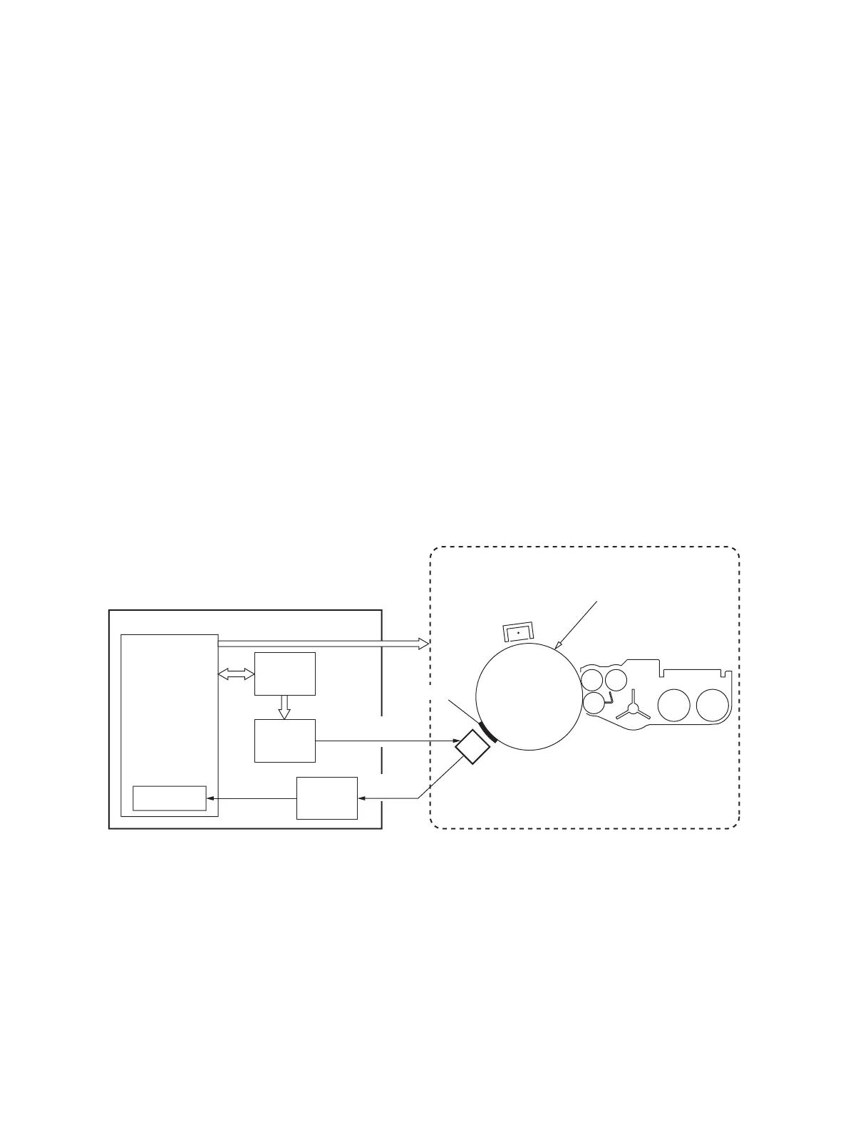
10.4.2 Construction
The construction of the control circuit is as follows.
• Image quality sensor:
This sensor emits the light corresponding to the voltage of the light source amount signal output
from the control section onto the drum, and outputs the voltage corresponding to the reflected light
amount of the drum and the test pattern (toner image) on the drum.
• Control section (LGC board):
This section performs image quality control mainly with the main CPU, which outputs the light
source amount signal (CTDVR-1A) of the image quality sensor by a D/A converter, and converts the
reflected light amount signal (CTDS-1) into a digital signal by mean of the A/D converter embedded
in the main CPU and reads it, and then sets the image formation condition based on the read result.
• Image formation process system:
This system consists of the process of charging, laser exposing and developing. Each process is
operated based on the image formation condition set by the control section. When image quality
control is performed, the laser unit exposes the test pattern on the drum.
Fig. 10-3
Image formation process system
LGC board
IC58
Main CPU
Laser exposure
Main charger
Drum
Developing
Test pattern
Image quality sensor
Reflected light
amount signal
(
CTDS-1 signal
)
Light source amount signal
(
CTDVR-1A signal
)
A/D converter
IC18
D/A converter
Various image formation conditions
IC56
ASIC
CTDVD-1A
CTDVC-1A
IC12, 98
Operational
amplifier circuit

 Loading...