11
© 2009 - 2011 TOSHIBA TEC CORPORATION All rights reserved e-STUDIO555/655/755/855
DEVELOPER UNIT
11 - 11
11.5.2 Operation of auto-toner sensor
1. Functions of the auto-toner sensor
- Initializing function: When the copier is set up or when the developer material is replaced
The automatic adjustment is made so that the output of the auto-toner sensor (input value of the
main-CPU) will be 2.45 to 2.85V for the toner density of new developer material.
- Toner density stabilizing function: During the printing operation
Through the following phases, the toner density is kept constant.
The toner is consumed.
→ The toner density is lowered.
→ The output change of the auto-toner sensor caused by humidity is detected.
→ The new toner transport motor, new toner supply motor and hopper motor are driven.
(The new toner supply motor and the hopper motor are driven only when the new toner is left in
the toner cartridge and also the front cover (upper) is closed.)
→ The toner is supplied to the developer unit from the sub-hopper (toner cartridge) and the
recycle toner hopper.
- Detection and release of empty status of the developer unit
The empty status of the developer unit is detected in the following procedure.
The new toner supply motor and the new toner transport motor are driven.
→ The output value of the auto-toner sensor remains the same.
→ The toner density is not changed.
→ The developer unit is judged as empty.
The empty status of the developer unit is released in the following procedure.
The new toner supply motor and the new toner transport motor are driven.
→ The new toner is supplied to the developer unit from the toner cartridge.
→ The output value of the auto-toner sensor is changed.
→ The toner density returns to its normal value.
→ The empty status of the developer unit is released.
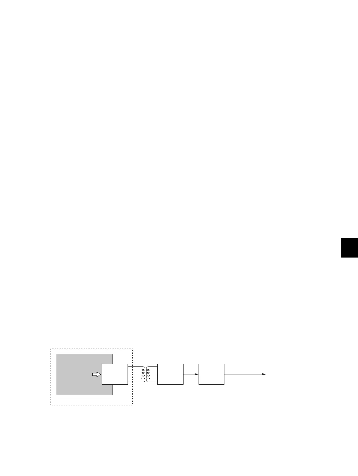
2. Auto-toner sensor drive circuit
The auto-toner sensor is composed of the following circuits.
- Drive winding:
Magnetic head (primary side) with a high-frequency magnetic field, which forms a magnetic
circuit in the developer material
- Detection winding:
Receiving the changes in the magnetic resistance of the developer material via a magnetic circuit
(secondary side)
- DC conversion circuit:
Converting the high-frequency output from the detection winding to a DC signal (auto-toner
output ATS-1A)
Fig. 11-8
Developer material
Magnetic resistance
Drive
winding
Detection
winding
DC
conversion
circuit
Auto-toner sensor
output
To the main-CPU
(
LGC board
)
ATS-1A
Magnetic circuit
Magnetic resistance
Developer material

 Loading...