EasyManua.ls Logo

Toshiba e-studio555 User Manual

Toshiba e-studio555
404 pages
To Next Page IconTo Next Page
To Previous Page IconTo Previous Page
Page #97 background imageLoading...
Page #97 background image
4
© 2009 - 2011 TOSHIBA TEC CORPORATION All rights reserved e-STUDIO555/655/755/855
GENERAL OPERATION
4 - 1
4. GENERAL OPERATION
4.1 Overview of Operation
4.2 Description of Operation
4.2.1 Warming-up
1. Initialization
Turning the power ON
The IH coil is turned ON.
The set number "1" reproduction ratio "100%" and "WAIT WARMING UP" appears.
The fan motors are turned ON.
Initialization of the scanning system
- The carriage moves to the home position and stops.
- The carriage moves to the peak detection position.
- The exposure lamp (EXP) is turned ON.
- Peak detection (a white color is detected by the shading correction plate)
- The exposure lamp (EXP) is turned OFF.
- The carriage moves to the home position.
Initialization of the feeding system
- Each drawer tray goes up
Initialization of the writing system
- The polygonal motor (M2) rotates at a high speed. (e-STUDIO755/855)
- The polygonal motor (M2) rotates at a low speed. (e-STUDIO555/655)
- The beam position is controlled. (e-STUDIO755/855)
Other
- The main charger cleaner operates.
2. Pre-running operation
The pre-running operation starts when the temperature of the fuser roller surface reaches a certain
degree. (Pre-running is not performed when the fuser roller is already hot enough.)
The fuser motor (M3) is turned ON.
- The fuser roller rotates.
The drum motor (M11) is turned ON.
- The drum rotates.
The used toner transport motor (M9) is turned ON
- The used toner transport auger rotates.
Image quality control
- It charges the drum and detects the drum surface potential to set the optimal condition for
outputting the image.
- It forms a patch on the drum and reads out its reflective ratio to set the optimal condition.
3. When the surface temperature of the fuser roller becomes sufficient for fusing;
The IH coil (IH-COIL) is turned OFF.
The set number "1" and "READY" are displayed.
Copier operation
Operation during warming-up, pre-running and standby
Copying operation
Automatic feed copying by pressing [START] button
Bypass copying
Interrupt copying

Table of Contents

Other manuals for Toshiba e-studio555

Question and Answer IconNeed help?

Do you have a question about the Toshiba e-studio555 and is the answer not in the manual?

Toshiba e-studio555 Specifications

Power IconPower
power supply120 Volts; 20 Amps
power consumptionMaximum 2.0kW
warm-up timeAppx. 130 Seconds
Printing and Copying IconPrinting and Copying
copy/print resolution2400 x 600 dpi
copy/print speed55 / 65 / 75 / 85 cpm
print speed55 / 65 / 75 / 85 ppm
Scanning IconScanning
scan speed80 spm LT-Size @300 dpi
scan resolution150 dpi, 200 dpi, 300 dpi, 400 dpi, 600 dpi
file formatTIFF, PDF, JPEG, XPS, MS Word, MS Excel, Searchable PDF w/ Adv. Scanning option
Memory and Storage IconMemory and Storage
memory1GB RAM, 60 GB HDD
fax memory transmission500MB (HDD)
reception500MB (HDD)
Connectivity IconConnectivity
connectivityEthernet 10/100BaseT, USB 2.0, 802.11b/g Wireless LAN, Bluetooth (HCRP)
protocol supportIPX/SPX, TCP/IP (IPV4/V6), EtherTalk, AppleTalk PAP, LPR/LPD, IPP w/Authentication, Port 9100
operating systemsWindows 2000/XP/2003/Vista/2008, Mac X OS 10.2.4/10.3/10.4/10.5, UNIX, Linux, CUPS
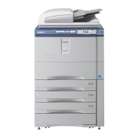
Weight and Dimensions IconWeight and Dimensions
dimensions28” x 31” x 46” (W x D x H)
weight462 lbs
standard paper supply2 x 500-Sheet Drawer; 2 x 1, 250-Sheet Tandem Drawer; 100-Sheet Stack Feed Bypass

Summary

TOSHIBA Service Manual

Specifications, Accessories, Options, and Supplies

Details machine specifications, included accessories, optional components, and consumables.

Outline of the Machine

Provides sectional views and electric parts layout of the machine's internal structure.

Symbols and Functions of Various Components

Explains symbols and functions of motors, sensors, switches, and PC boards.

Copy Process Overview

Describes the general process of image formation and copying.

General Operation Guide

Covers machine operation, warming-up, states, and abnormality detection.

Control Panel Functions

Details the control panel, display messages, and state relations.

Scanning Section Operation

Explains the function, construction, and operation of the scanning system.

Laser Optical Unit Details

Describes the laser optical unit, its components, control circuits, and safety precautions.

Paper Feeding System

Details the paper feeding system, its functions, operation, and motors.

Process Related Section

Explains components related to image formation: chargers, sensors, transformers.

Drum and Cleaner Unit

Describes the drum, cleaner unit, their functions, and disassembly.

Developer Unit Components

Covers developer unit construction, functions, motor circuits, and disassembly.

Transfer and Transport Unit

Explains the transfer belt, transport system, functions, and disassembly.

Fuser Unit Details

Covers fuser unit outline, operation, functions, control circuits, and disassembly.

Exit/Reverse Section Operations

Details the exit/reverse section functions, driving, operation, and disassembly.

Reversing Automatic Document Feeder (RADF)

Explains RADF functions, paper path, drive, size detection, circuits, and disassembly.

Power Supply Unit Information

Describes the power supply unit construction, operation, output channels, and fuses.

PC Boards Identification

Shows the layout and identification of various PC boards.

External Counters Interface

Details the interface and signals for external counters like coin/key counters.

Revision Record

Lists changes and updates made in different versions of the manual.

Related product manuals