13
© 2009 - 2011 TOSHIBA TEC CORPORATION All rights reserved e-STUDIO555/655/755/855
FUSER UNIT
13 - 5
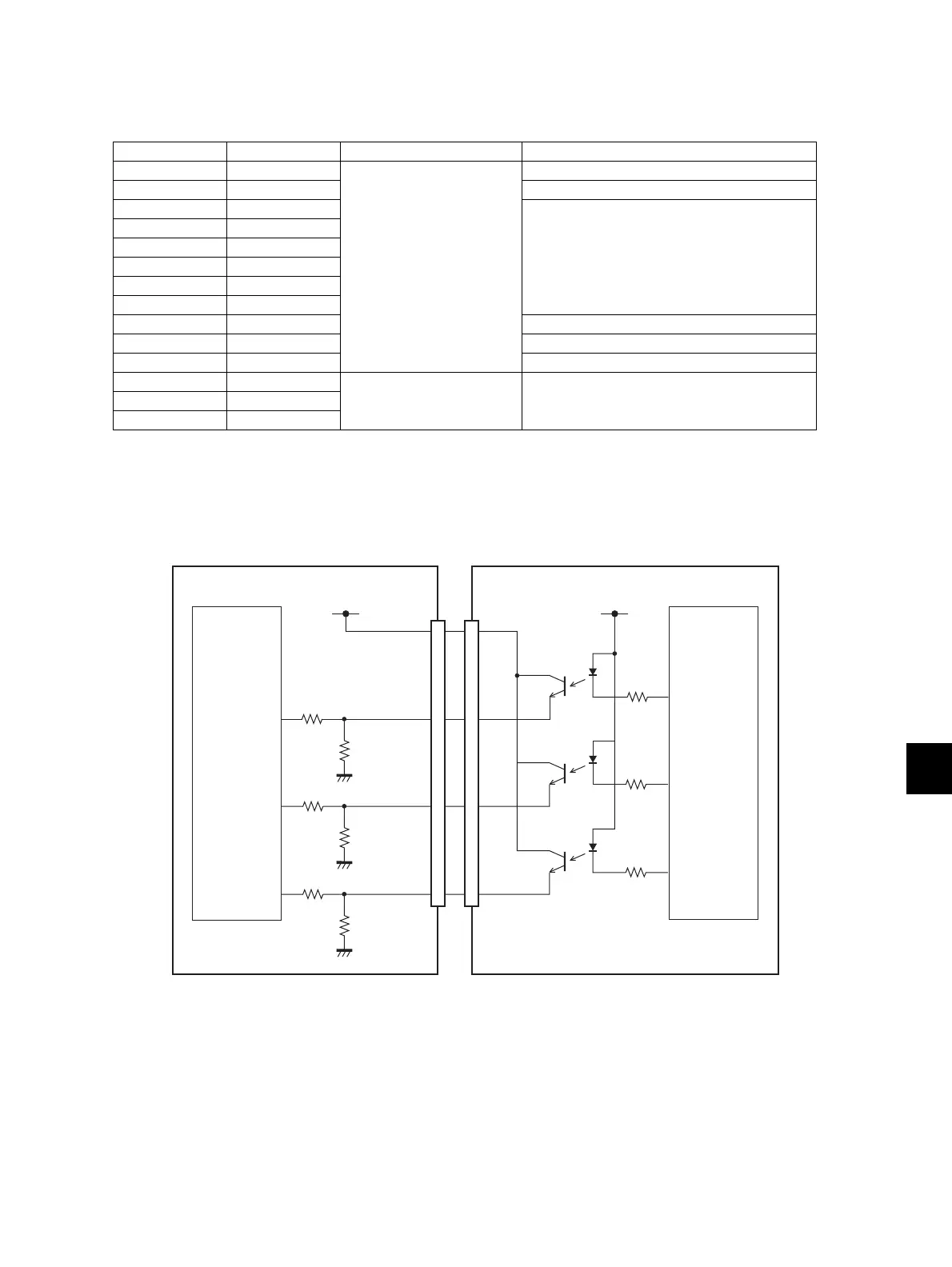
13.4.3 IH control circuit interface
The IH control circuit uses a photocoupler as an insulator against the secondary circuit.
The interface signals are as followed.
13.4.4 Abnormality in the IH control circuit
When an abnormality is detected in the IH control circuit, it stops the power supply to the IH coil and
displays a message "call for service".
Fig. 13-5
Connector No. Signal Direction Definition
CN455-1 IH2ON LGC board to IH board IH coil energization permitting signal
CN455-2 +5VSW -
CN455-3 H1PWR1 Switching signal of power setting
CN455-4 H1PWR2
CN455-5 H1PWR3
CN455-6 H2PWR1
CN455-7 H2PWR2
CN455-8 H2PWR3
CN455-9 IH1ON IH coil energization permitting signal
CN455-10 SG -
CN455-11 IHDUTY Duty ratio changing signal
CN455-12 IHERR1 IH board to LGC board IH status signal
CN455-13 IHERR2
CN455-14 IHERR3
Vcc
IH board
+5VSW
H1ERR2-0
H1ERR3-0
H1ERR1-0
LGC board
CPU
IC56
ASIC

 Loading...