EasyManua.ls Logo

Trane Tracer MP580 User Manual

Trane Tracer MP580
144 pages
To Next Page IconTo Next Page
To Previous Page IconTo Previous Page
Page #133 background imageLoading...
Page #133 background image
Examples of network variable bindings
CNT-SVP01C-EN 123
Use the Rover service tool to create bindings. (See the Rover Operation
and Programming guide, EMTX-SVX01C-EN.) Using the Rover service
tool, select the network variable from the Tracer MP581 and then select
the Tracer MP503. The Rover service tool shows you only the variables in
the Tracer MP503 of the SNVT that matches the variable you selected in
the Tracer MP581.
Table 16 shows the bindings needed.
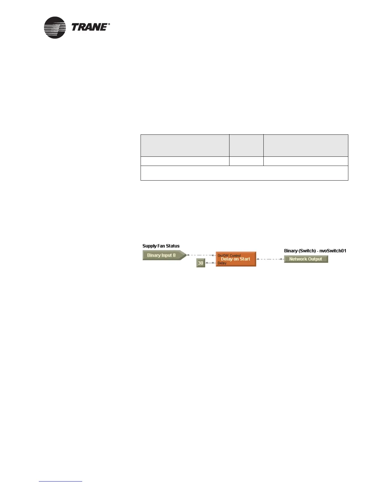
Custom programming in the Tracer MP581 controls nvoSwitch01. Write
a custom program to control nvoSwitch01 on when the AHU is on, and
has been on for 30 seconds, and off when the AHU is off. The network
binding passes the command to the binary output on the Tracer MP503.
See Figure 81 for a sample program written in the TGP editor.
Figure 81. Program for example 3
Example 4: Use a sensor reading on a Tracer MP503 to
control a pump VFD on a Tracer MP581
In this example, a Tracer MP581 controller is controlling the variable fre-
quency drive (VFD) of a chilled water pump. We want to use a differential
pressure sensor (4–20 mA output) to control the speed of this pump.
Unfortunately, the differential pressure sensor is located more than
1,000 ft away from the pump, so it cannot be wired directly to the univer-
sal input on the Tracer MP581. Install a Tracer MP503 I/O module to
read the differential pressure and then use network bindings to send the
pressure value to the Tracer MP581 controlling the chilled water pump
VFD.
Figure 82 on page 124 shows the Comm5 network for this example.
Table 16. Bindings for example 3
Network variable output on
the Tracer MP581
Network variable input on
the Tracer MP503
nvoSwitch01
1
binds to nviBOP1Request
1
The Tracer MP581 has 40 generic binary (SNVT_switch) network variable outputs
available for binding (nvoSwitch01 through nvoSwitch40).

Table of Contents

Other manuals for Trane Tracer MP580

Question and Answer IconNeed help?

Do you have a question about the Trane Tracer MP580 and is the answer not in the manual?

Trane Tracer MP580 Specifications

General IconGeneral
BrandTrane
ModelTracer MP580
CategoryController
LanguageEnglish

Summary

Chapter 1 Overview

Using Rover service tool

Learn to use the Rover service tool for device setup and configuration.

Accessing the Tracer MP580/581

Steps to connect and access the controller via the Rover service tool.

Chapter 2 Viewing status

Viewing the status of binary and analog outputs

Monitor the current state of hardware outputs on the controller.

Overriding binary and analog outputs

Manually change the value of binary and analog outputs.

Changing binary and analog variables

Modify the values of variables through the Displays tab.

Chapter 3 Configuring the Tracer MP580/581

Configuring inputs

Set up universal, binary, analog, and pulse inputs for the controller.

Configuring outputs

Configure binary and analog hardware outputs with descriptors and times.

Configuring variables

Set up binary and analog variables for data management and control.

Configuring user security

Set up security privileges for users to access controller functions.

Chapter 4 Using the Schedule application

Setting up the daily schedule

Define daily start and stop times for occupancy schedules.

Controlling the occupancy mode of the Tracer MP580/581

Manage controller occupancy modes from various sources.

Chapter 5 Using the Calculations application

Setting up a calculation

Define calculation name, input type, conversion factor, and units.

Chapter 6 Graphical programming overview

Opening the TGP editor

Access the Tracer Graphical Programming editor to create programs.

Blocks

Understand the fundamental programming blocks used in the TGP editor.

Keyboard short cuts

Learn keyboard shortcuts for efficient work with programs and blocks.

Chapter 7 Creating a graphical program

Editing program properties

Define program name, execution frequency, and description.

Connecting blocks using wired connections

Establish data flow between blocks using wired connections.

Chapter 8 Using the Occupancy and PID blocks

Using the Occupancy block

Utilize the Occupancy block for determining values and states of outputs.

Using the PID block

Implement proportional, integral, derivative control loops for modulating devices.

Chapter 9 Implementing a graphical program

Compiling a program

Check programs for errors and prepare them for download.

Downloading a program

Transfer compiled programs to the Tracer MP580/581 controller.

Chapter 10 Network variable bindings

Overview

Understand data sharing between devices on a Comm5 network.

Examples of network variable bindings

Explore common uses of bindings in Tracer MP580/581 applications.

Related product manuals