I
I I
Removing the Shock Absorber Rubbers. Engage the clutch locking tool (See
Fig.
33)
in the clutch housing and clutch centre. Slide the driveshaft adaptor, Part
I
No.
Z90
(Fig.
32)
onto the engine mainshaft, engaging the "dogged' end into the
I
1
exposed sprocket splines.
On the
6T
model the mainshaft nut must be replaced to
I
keep the adaptor in position for the next operation. Flace a suitable spanner onto the
adaptor hexagon so that the mainshaft can be rotated anti-clockwise to compress
1
the other rubbers.
Ease
the rebound rubbe- out and then relea;e the pressure on
I
1
the spanner when the drive rubbers can be removed.
Although this chapter deals with the dismantling of the clutch and shock absorber,
it
is
desirable at this point to explain the assembly of the shock absorber unit.
I
Replacing New Shock Absorber Rubbers. Position the four drive rubbers
I
(See Fig.
29)
and exert pressure on the spanner
to
replace the rebound rubbers.
I
Outer Retaining Pla:e. Ensure that the rubbers are correctly positioned and
i
fully in their housing and then replace the plate, securing with the four
2
B.A.
countersunk screws.
I
1
To
d~srnontle the remainder
of
the clutch proceed as follows:-
!
Clutch Push Rod. Remove from mainshaft.
1
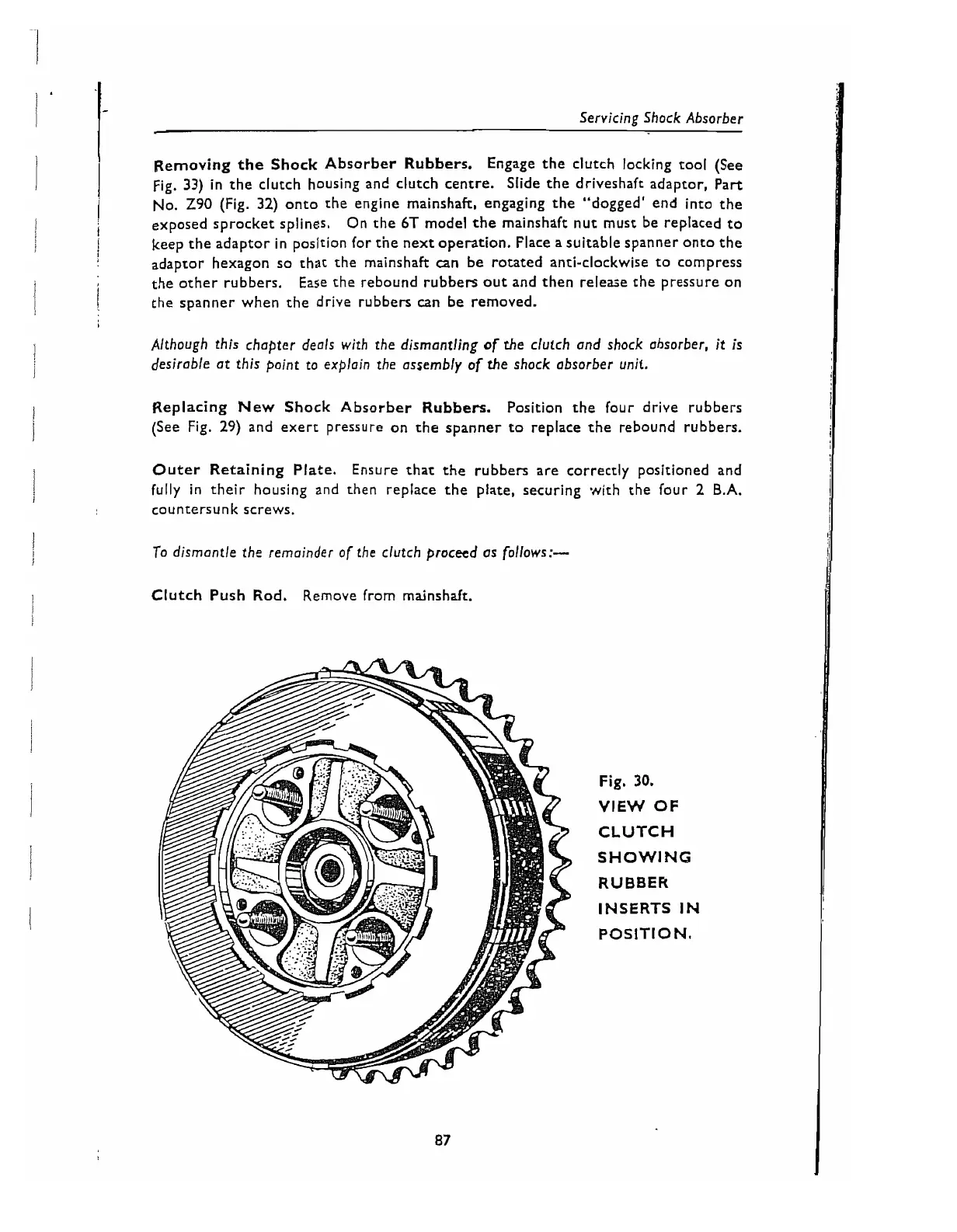
Fig.
30.
VIEW OF
CLUTCH
SHOWINC;
RUBBER
INSERTS
IN
POSITION.
 Loading...