VCU118 Board User Guide 14
UG1224 (v1.0) December 15, 2016
www.xilinx.com
Chapter 2: Board Setup and Configuration
Default Switch and Jumper Settings
Switches
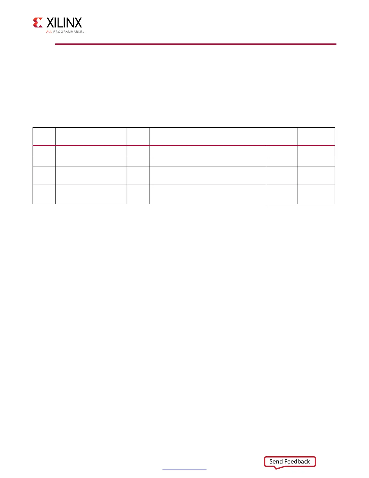
Default switch settings are listed in Table 2-2. Switch locations are shown in Figure 2-1.
Table 2-2 also references the respective schematic page numbers.
Table 2-2: Default Switch Settings
Switch Function Default Comments
Figure 2-1
Callout
Schematic
Page
SW1 SPST slide switch OFF Board shipped with power switch off 30 59
SW12 4-pole GPIO 0000 Positions 1-4, GPIO 26 55
SW15 4-pole configuration 0000
Positions 1-4, Zynq-7000 AP SoC System
Controller U111
28 49
SW16 4-pole configuration 0101
Position 1, System Controller Enable
Positions 2-4, FPGA U1 mode M[2:0]
35 3
Notes:
1. DIP switches are active-High (connected net is pulled High when DIP switch is closed).

 Loading...


