VCU118 Board User Guide 87
UG1224 (v1.0) December 15, 2016
www.xilinx.com
Chapter 3: Board Component Descriptions
CPU Reset Pushbutton
[Figure 2-1, callout 25]
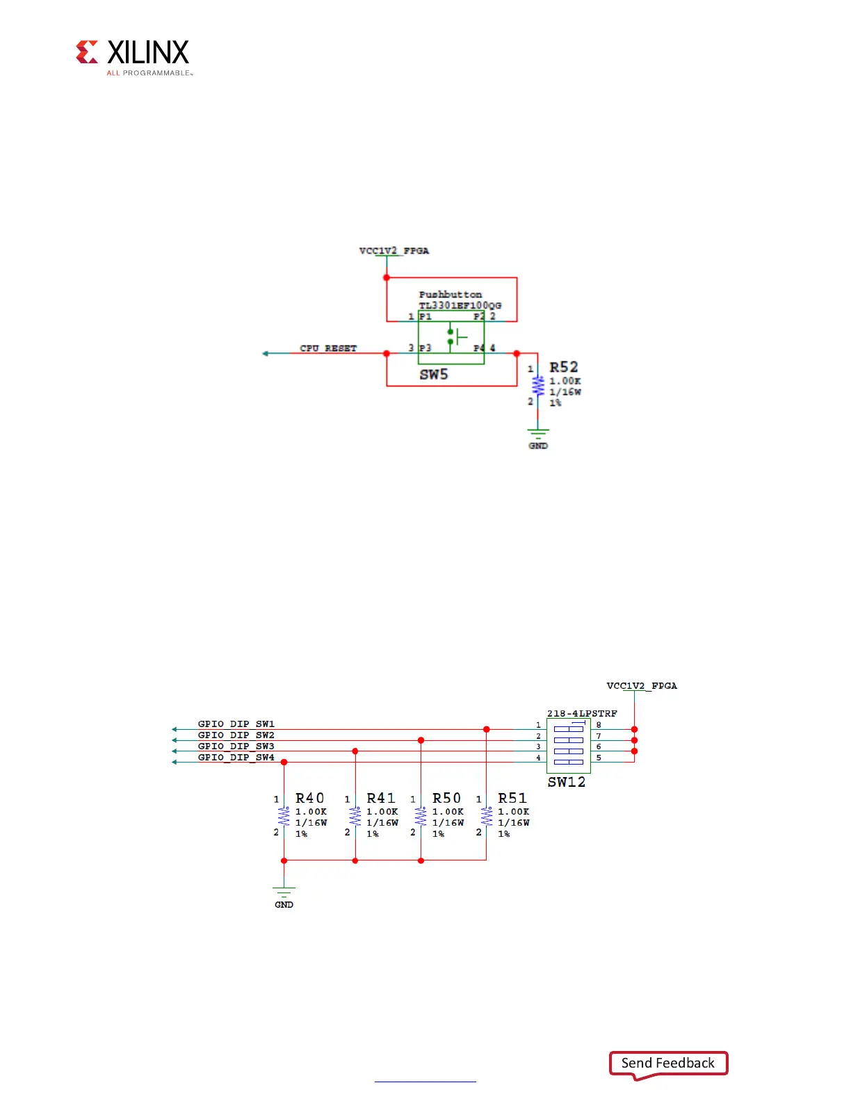
Figure 3-21 shows the CPU reset pushbutton circuit.
GPIO DIP Switch
[Figure 2-1, callout 26]
Figure 3-22 shows the GPIO DIP switch circuit.
X-Ref Target - Figure 3-21
Figure 3-21: CPU Reset Pushbutton
X-Ref Target - Figure 3-22
Figure 3-22: GPIO DIP Switch

 Loading...


