VCU118 Board User Guide 75
UG1224 (v1.0) December 15, 2016
www.xilinx.com
Chapter 3: Board Component Descriptions
FireFly Connector
[Figure 2-1, callout 41]
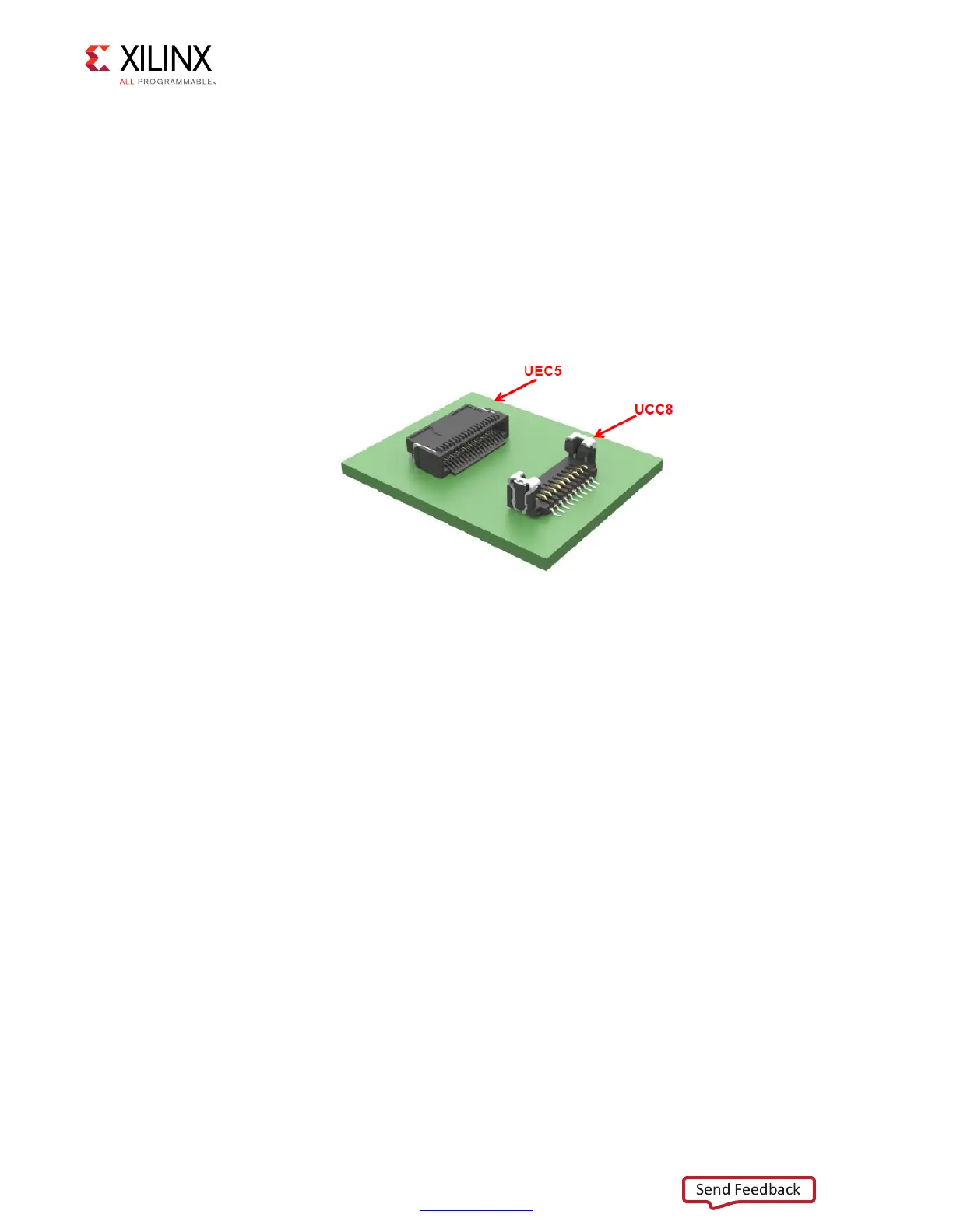
The VCU118 board contains a 4x28 Gb/s FireFly composite connector pair J6. The FireFly
connector system is a two part connector designed for applications up to 28 Gb/s. It is
based on two connectors, a micro high-speed edge connector (UEC5 Series, shown rear left)
with two rows of 19 positions providing 12 differential lanes and a 10-position positive latch
control signal and power connector (UCC8 Series, shown front right). Figure 3-14 shows the
connector pair.
X-Ref Target - Figure 3-14
Figure 3-14: FireFly Connector System

 Loading...


