VCU118 Board User Guide 85
UG1224 (v1.0) December 15, 2016
www.xilinx.com
Chapter 3: Board Component Descriptions
User I/O
[Figure 2-1, callouts 24, 25, 26]
The VCU118 board provides these user and general purpose I/O capabilities:
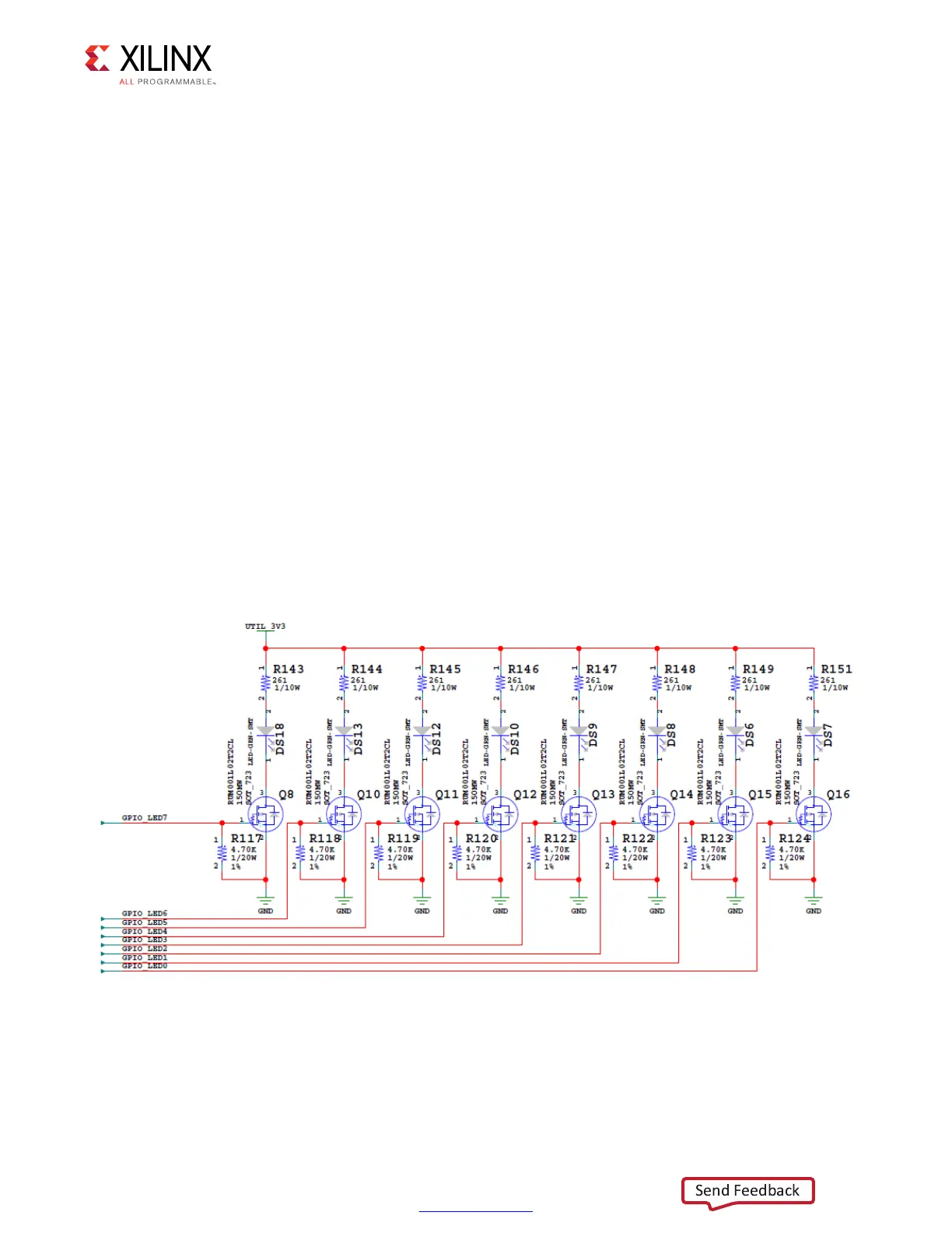
• Eight user LEDs (callout 24)
°
GPIO_LED[7-0]: DS31, DS32, DS33, DS10, DS19, DS8, DS6, DS7
• Five user pushbuttons and CPU reset switch (callout 25)
°
GPIO_SW [NESWC]: SW10, SW9, SW8, SW6, SW7
°
CPU_RESET: SW5 (callout 25)
• 4-position user DIP switch (callout 26)
°
GPIO_DIP_SW[3:0]: SW12
User GPIO LEDs
[Figure 2-1, callouts 24]
Figure 3-19 shows the GPIO LED circuit.
X-Ref Target - Figure 3-19
Figure 3-19: User LEDs

 Loading...


