VCU118 Board User Guide 78
UG1224 (v1.0) December 15, 2016
www.xilinx.com
Chapter 3: Board Component Descriptions
10/100/1000 Mb/s Tri-Speed Ethernet PHY
[Figure 2-1, callout 19]
The VCU118 evaluation board uses the TI PHY device DP83867ISRGZ (U7) for Ethernet
communications at 10 Mb/s, 100 Mb/s, or 1000 Mb/s. The board supports SGMII mode only.
The PHY connection to a user-provided Ethernet cable is through RJ-45 connector J10, a
Wurth 7499111221A with built-in magnetics and status LEDs.
On power-up, or on reset, the PHY is configured to operate in SGMII mode with PHY
address[4:0] = 00011.
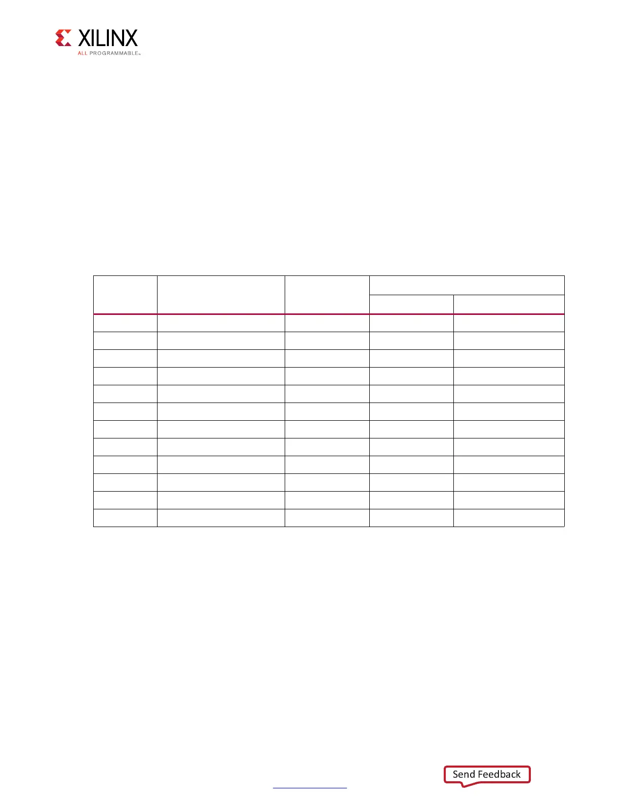
Table 3-25 lists the FPGA U1 to U7 DP83867ISRGZ Ethernet PHY connections.
Table 3-25: FPGA U1 to Ethernet PHY U7 Connections
FPGA (U1)
Pin
Net Name I/O Standard
DP83867ISRGZ U7
Pin Name
AR23 PHY1_MDIO LVCMOS18 17 MDIO
AV23 PHY1_MDC LVCMOS18 16 MDC
AR24 PHY1_PDWN_B_I_INT_B_O LVCMOS18 44 INT_PWDN
AV21 PHY1_SGMII_IN_N LVCMOS18 28 TX_D1_SGMII_SIP
AU21 PHY1_SGMII_IN_P LVCMOS18 27 TX_D0_SGMII_SIN
AV24 PHY1_SGMII_OUT_N LVCMOS18 36 RX_D3_SGMII_SON
AU24 PHY1_SGMII_OUT_P LVCMOS18 35 RX_D2_SGMII_SOP
AU22 PHY1_SGMII_CLK_N LVCMOS18 34 RX_D1_SGMII_CON
AT22 PHY1_SGMII_CLK_P LVCMOS18 33 RX_D0_SGMII_COP
BA21 PHY1_RESET_B LVCMOS18 43 RESET_B
AR22 PHY1_GPIO_0 LVCMOS18 39 GPIO_2
AU23 PHY1_CLKOUT LVCMOS18 18 CLK_OUT

 Loading...


