VCU118 Board User Guide 79
UG1224 (v1.0) December 15, 2016
www.xilinx.com
Chapter 3: Board Component Descriptions
Ethernet PHY Status LEDs
[Figure 2-1, callout 20]
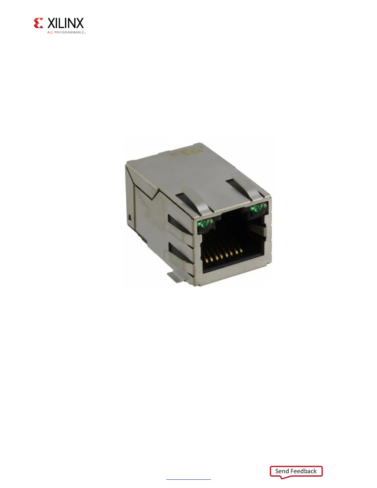
Two Ethernet PHY status LEDs are integrated into the metal frame of the J10 RJ-45
connector. These LEDs are visible on the left edge of the VCU118 board when it is installed
into a PCIe slot in a PC chassis. The two PHY status LEDs are visible within the frame of the
RJ45 Ethernet jack as shown in Figure 3-16. As viewed from the front opening, the left green
LED is the link activity indicator, the right green LED is the 1000BASE-T link mode indicator.
A separate discrete LED on top of the board (DS27) indicates link established.
Details about the tri-mode Ethernet MAC core are provided in Tri-Mode Ethernet MAC
LogiCORE IP Product Guide (PG051) [Ref 9]. The TI DP83867ISRGZ data sheet can be found
on the TI website [Ref 25].
X-Ref Target - Figure 3-16
Figure 3-16: VCU118 Ethernet PHY Status LEDs

 Loading...


