3.16 Wiring Checklist
114 YASKAWA SIEPC71061753C GA500 Technical Manual
3.16 Wiring Checklist
Wire the drive, examine these items, then do a test run.
Table 3.19 Power Supply Voltage
Checked No. Item to Check
1 The power supply voltage must be in the input voltage specification range of the drive.
Table 3.20 Main Circuit Wiring
Checked No. Item to Check
1 • Put the power supply through a molded-case circuit breaker (MCCB) before it gets to the drive input.
• Connect an applicable MCCB.
2 Correctly wire the power supply to drive terminals R/L1, S/L2, and T/L3, or L/L1 and N/L2.
3 Correctly wire the drive and motor together.
The motor lines and drive output terminals U/T1, V/T2, and W/T3 must align to make the correct phase order.
Note:
If the phase order is incorrect, the drive will rotate in the opposite direction.
4 Use 600 V heat resistant indoor PVC wire for the power supply and motor lines.
Note:
Wire gauge recommendations assume use of 600 V class 2 heat-resistant indoor PVC wire.
5 Use the correct wire gauges for the main circuit.
Note:
• When the wiring distance between the drive and the motor is long, use this formula for the voltage drop in the wire:
Motor rated voltage (V) × 0.02 ≥ √3 × wire resistance (Ω/km) × wiring distance (m) × motor rated current (A) × 10
-3
• When the cable between the drive and motor is longer than 50 m (164 ft), use parameter C6-02 [Carrier Frequency Selection] to
decrease the carrier frequency.
6 Correctly ground the drive.
7 Tighten the main circuit and grounding terminal screws of the drive to a correct tightening torque.
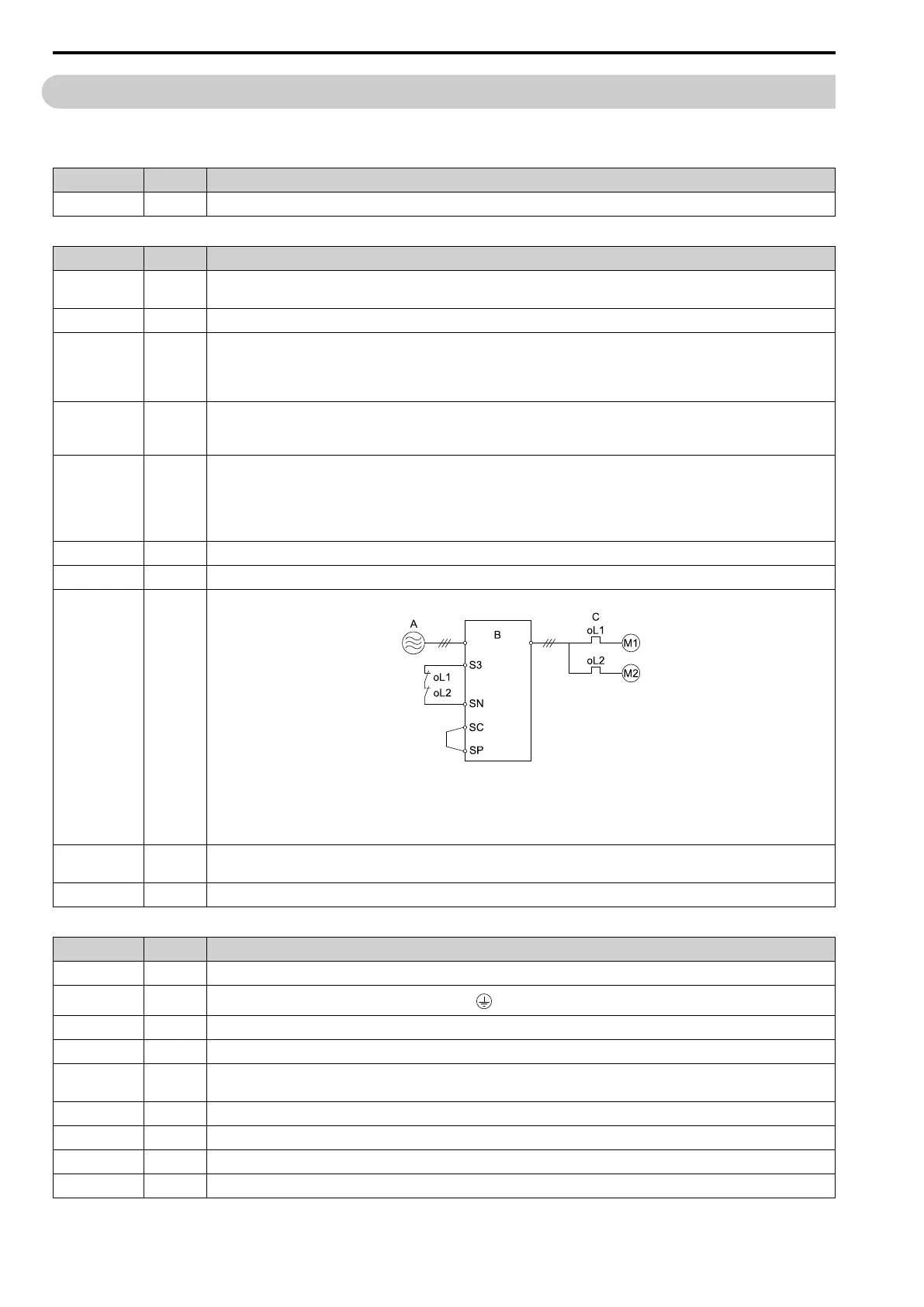
8 When operating more than one motor from one drive, set up overload protection circuits.
A - Power Supply
B - Drive
C - oL1, oL2: Thermal overload relay
Note:
Set H1-03 = 25 [Terminal S3 Function Selection = External Fault (NC-Always-Coast)].
9 When you use a braking resistor or a braking resistor unit, install an electromagnetic contactor (MC).
Correctly install the resistor and make sure that overload protection uses the MC to shut off the power supply.
10 Make sure you did not install phase advancing capacitors, input noise filters, or ELCBs, GFCIs, RCM/RCDs on the output side of the drive.
Table 3.21 Control Circuit Wiring
Checked No. Item to Check
1 Use twisted-pair cables for all drive control circuit wiring.
2
Ground the shields of shielded wiring to the ground terminal .
3 For 3-Wire sequence, set parameters for MFDI terminals and wire control circuits.
4 Correctly install any options.
5 Examine the drive for other wiring errors.
Only use a multimeter to check wiring.
6 Tighten the control circuit terminal screws of the drive to a correct tightening torque.
7 Pick up all wire clippings.
8 Make sure that none of the wires on the terminal block touch other terminals or connections.
9 Make sure that you isolate the control circuit wiring from main circuit wiring in the control panel or in a duct.

 Loading...


