Troubleshooting
7
7.10 Troubleshooting Without Fault Display
YASKAWA SIEPC71061753C GA500 Technical Manual 299
◆ The Motor Does Not Rotate after You Enter a Run Command
Causes Possible Solutions
The drive is not in Drive Mode. 1. Make sure that the READY LED on the keypad is ON.
2. If the READY LED is OFF, push and hold the ESC Key to go back to the frequency
reference screen (the initial screen).
The drive stopped and you pushed to transfer the Run command
source to the keypad.
Do one of these two:
• Push .
• Re-energize the drive.
Note:
When must not change the Run command source, set o2-01 = 0 [LO/RE Key
Function Selection = Disabled].
Auto-Tuning completed. Push and hold the ESC Key to go back to the frequency reference screen (the initial screen).
Note:
When Auto-Tuning completes, the drive changes to Programming Mode. The drive will not
accept a Run command unless the drive is in Drive Mode.
The drive received a Fast Stop command. Turn off the fast stop input signal.
The settings for the source that supplies the Run command are incorrect. Set b1-02 [Run Command Selection 1] correctly.
The frequency reference source is not set correctly. Set b1-01 [Frequency Reference Selection 1] correctly.
There is defective wiring in the control circuit terminals. • Correctly wire the drive control circuit terminals.
• View U1-10 [Input Terminal Status] for input terminal status.
The settings for voltage input and current input of the master frequency
reference are incorrect.
Examine these analog input terminal signal level settings:
• Terminal A1: H3-01 [Terminal A1 Signal Level Select]
• Terminal A2: DIP switch S1 and H3-09 [Terminal A2 Signal Level Select]
The selection for the sinking/sourcing mode and the internal/external power
supply is incorrect.
• For sinking mode, close the circuit between terminals SC-SP with a wire jumper.
• For sourcing mode, close the circuit between terminals SC-SN with a wire jumper.
• For external power supply, remove the wire jumper.
The frequency reference is too low. • View U1-01 [Freq Reference].
• Increase the frequency reference to a value higher than E1-09 [Minimum Output Frequency].
The MFAI setting is incorrect. • Make sure that the functions set to the MFAI are correct. The frequency reference is 0 when
H3-02, H3-10 = 1 [MFAI Function Select = Frequency Gain] and voltage (current) is not
input.
• Use U1-13, U1-14 [Terminal A1, A2 Input Voltage] to make sure that the analog input values
set to terminals A1 and A2 are applicable.
You pushed .
Turn the Run command OFF then ON from an external input.
Note:
When you push during operation, the drive will ramp to stop. Set o2-02 = 0 [STOP
Key Function Selection = Disabled] to disable the function.
The 2-wire sequence and 3-wire sequence are not set correctly. • Set one of the parameters H1-03 to H1-07 [Terminals S3 to S7 Function Select] to 0 [3-Wire
Sequence] to enable the 3-wire sequence.
• If a 2-wire sequence is necessary, make sure that H1-03 to H1-07 ≠ 0.
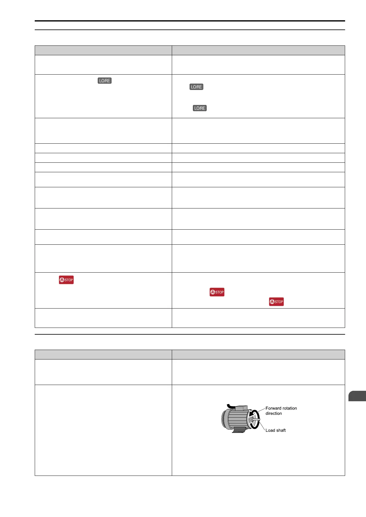
◆ The Motor Rotates in the Opposite Direction from the Run Command
Causes Possible Solutions
The phase wiring between the drive and motor is incorrect. • Examine the wiring between the drive and motor.
• Connect drive output terminals U/T1, V/T2, and W/T3 in the correct sequence to agree with
motor terminals U, V, and W.
• Switch two motor cables U, V, and W to reverse motor direction.
The forward direction for the motor is set incorrectly. • Connect drive output terminals U/T1, V/T2, and W/T3 in the correct sequence to agree with
motor terminals U, V, and W.
• Switch two motor cables U, V, and W to reverse motor direction.
Figure 7.1 Forward Rotating Motor
Note:
• For Yaskawa motors, the forward direction is counterclockwise when looking from the
motor shaft side.
• Refer to the motor specifications, and make sure that the forward rotation direction is
correct for the application. The forward rotation direction of motors can be different for
different motor manufacturers and types.

 Loading...


