Electrical Installation
3
3.3 Main Circuit Wiring
YASKAWA SIEPC71061753C GA500 Technical Manual 73
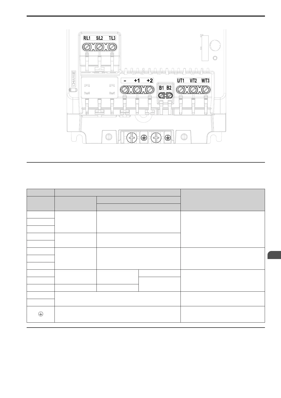
Figure 3.23 Configuration of Main Circuit Terminal Block (Three-Phase, With a Built-in EMC Filter)
◆ Main Circuit Terminal Functions
Refer to Table 3.2 for the functions of drive main circuit terminals.
Table 3.2 Main Circuit Terminal Functions
Terminal Name
Function
Model B001 - B018
2001 - 2082
4001 - 4060
R/L1
- Main circuit power supply input
To connect a commercial power supply.
S/L2
T/L3
L/L1
Main circuit power supply
input
-
N/L2
U/T1
Drive output Drive output To connect a motor.V/T2
W/T3
-
DC power input DC power input
-
+1 and +2: To connect a DC reactor.
Note:
Remove the jumper between terminals +1 and +2 to
connect a DC reactor.
+1
DC reactor connection
+2 - -
B1
Braking resistor connection To connect a braking resistor or braking resistor unit.
B2
Ground Wiring
To ground the drive.
• 200 V: D class grounding (ground to 100 Ω or less)
• 400 V: C class grounding (ground to 10 Ω or less)
◆ Wire Selection
Select the correct wires for main circuit wiring.
Refer to Main Circuit Wire Gauges and Tightening Torques on page 170 for wire gauges and tightening torques as
specified by European standards.
Refer to Main Circuit Wire Gauges and Tightening Torques on page 188 for wire gauges and tightening torques as
specified by UL standards.

 Loading...


