12.7 F: Options
602 YASKAWA SIEPC71061753C GA500 Technical Manual
12.7 F: Options
F parameters are used to set option cards, which function as interfaces for encoders, analog I/O, digital I/O, and
fieldbus communication.
◆ F1: Fault Detection in PG Speed Control
F1 parameters set the fault detection function in Speed Feedback (V/F Control). When A1-02 = 0 [Control
Method Selection = V/f], set H6-01 = 3 [Terminal RP Pulse Train Function = Speed Feedback (V/F Control)] to
enable this function. For speed feedback, connect the single-channel pulse signal from the PG encoder to pulse
train input terminal RP. Use the Slip Compensation signal to improve the accuracy of Speed Control. This
function is available for Motor 1.
WARNING! Sudden Movement Hazard. Do test runs and examine the drive to make sure that the command references are
correct. If you set the command reference incorrectly, it can cause damage to the drive or serious injury or death.
WARNING! Sudden Movement Hazard. Make sure that the host controller circuitry has correct safety design that will let you
keep control of the motor if the drive loses speed feedback. If you do not have control of the motor, it can cause serious injury or
death.
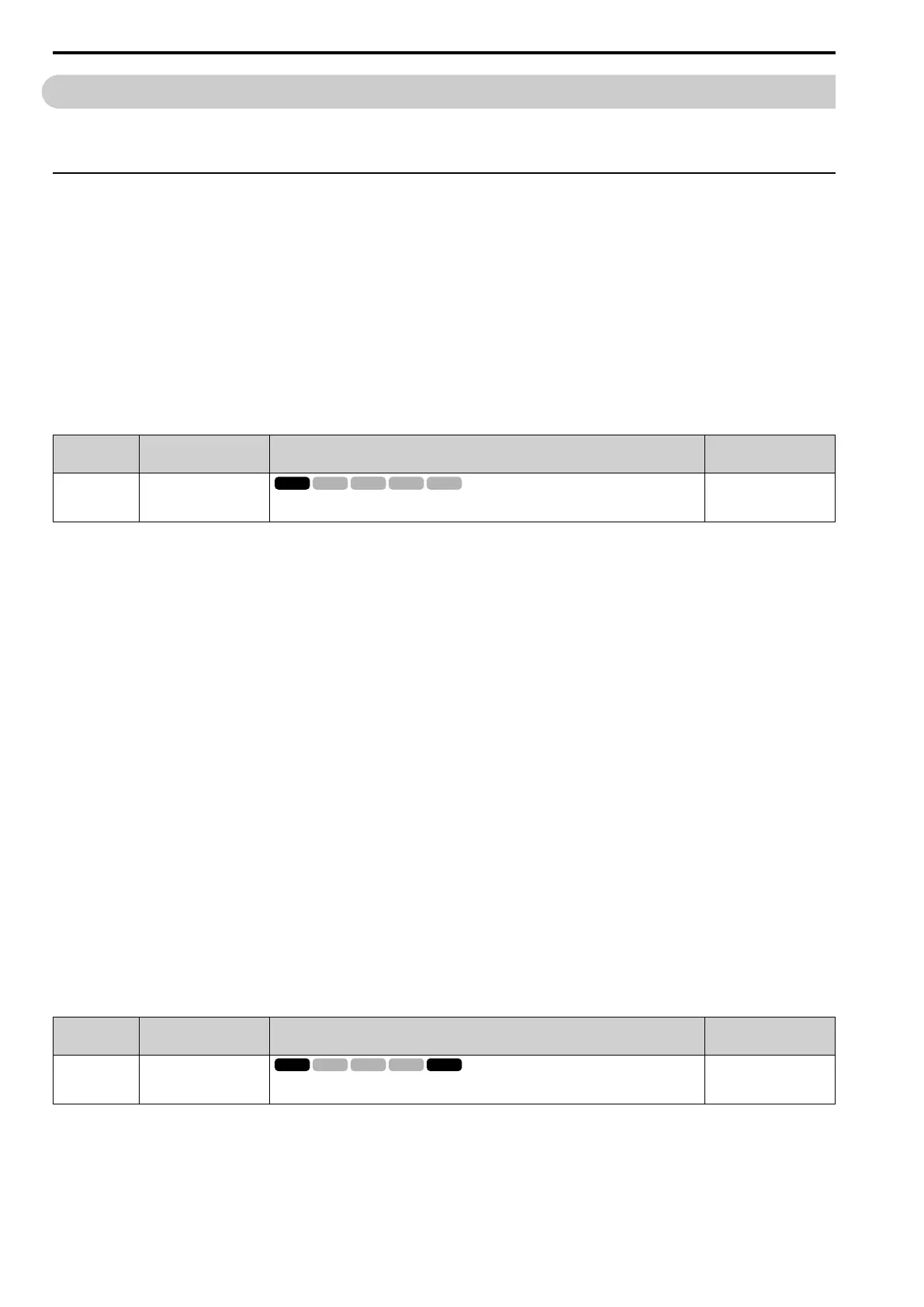
■ F1-02: Encoder Signal Loss Detect Sel
No.
(Hex.)
Name Description
Default
(Range)
F1-02
(0381)
Encoder Signal Loss Detect
Sel
Sets the method to stop the motor or let the motor continue operating when the drive detects PGo
[Encoder (PG) Feedback Loss].
1
(0 - 4)
If the drive does not detect ouput pulses from the encoder for the time set in F1-14 [Encoder Open-Circuit Detect
Time], it will trigger PGo.
Note:
• When A1-02 = 0 [Control Method Selection = V/f], set H6-01 = 3 [Terminal RP Pulse Train Function = Speed Feedback (V/F
Control)] to enable this parameter.
• Motor speed and load conditions can cause ov [Overvoltage] and oC [Overcurrent] faults.
0 : Ramp to Stop
The drive ramps the motor to stop in the deceleration time. The output terminal set for Fault [H2-01 to H2-03 =
E] activates.
1 : Coast to Stop
The output turns off and the motor coasts to stop. The output terminal set for Fault [H2-01 to H2-03 = E]
activates.
2 : Fast Stop (Use C1-09)
The drive stops the motor in the deceleration time set in C1-09 [Fast Stop Time]. The output terminal set for Fault
[H2-01 to H2-03 = E] activates.
3 : Alarm Only
The keypad shows PGo and the drive continues operation. Only use this setting in special conditions to prevent
damage to the motor and machinery. The output terminal set to Alarm [H2-01 to H2-03 = 10] activates.
4 : No Alarm Display
The drive continues operation and does not show PGo on the keypad. Only use this setting in special conditions to
prevent damage to the motor and machinery.
■ F1-03: Overspeed Detection Selection
No.
(Hex.)
Name Description
Default
(Range)
F1-03
(0382)
Overspeed Detection
Selection
Sets the method to stop the motor or let the motor continue to operate when the drive detects oS
[Overspeed].
1
(0 - 3)
When the motor speed is more than the value set in F1-08 [Overspeed Detection Level] for longer than the time
set in F1-09 [Overspeed Detection Delay Time] it will trigger oS.
0 : Ramp to Stop
The drive ramps the motor to stop in the deceleration time. The output terminal set for Fault [H2-01 to H2-03 =
E] activates.

 Loading...


