6.3 MEMOBUS/Modbus Communications
220 YASKAWA SIEPC71061753C GA500 Technical Manual
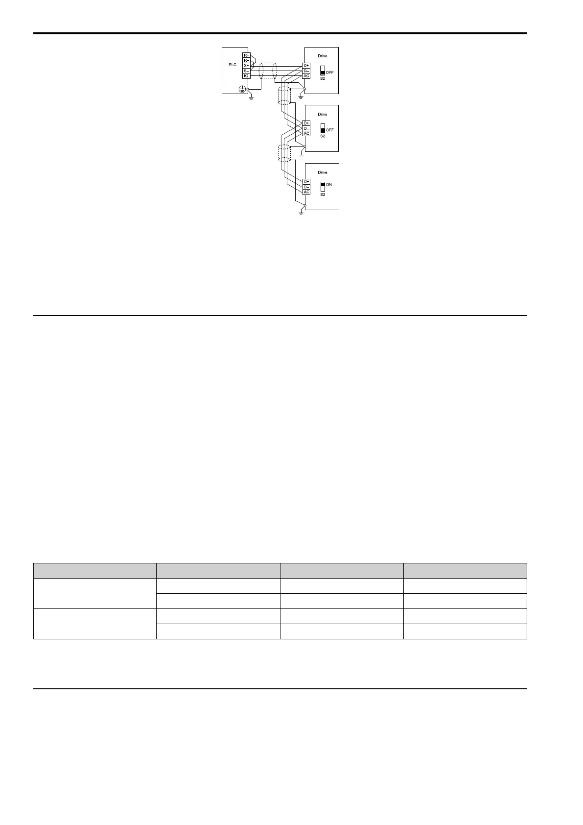
Figure 6.4 Wiring Diagram for More than One Drive
Note:
1. Set DIP switch S2 to the ON position on the last drive of the MEMOBUS/Modbus communication network to enable the termination
resistor.
2. For long cable runs or multi-floor installations, connect the shield to ground at only one device on the network (at the PLC, if
possible) to prevent ground loops. When you remove the shield from the ground terminal, it can increase the communication quality
in some drive installation locations.
◆ MEMOBUS/Modbus Drive Operations
Drive parameters will apply to the settings when the drive is running during MEMOBUS/Modbus
communications. This section gives information about the available functions and their related parameters.
■ Executable Functions
A PLC can do these operations with MEMOBUS/Modbus communications. Parameter settings (except H5-xx) do
not have an effect on the availability of these operations.
• Monitor the drive status and operate the drive
• Set and view parameters
• Fault Reset
• Multi-function input settings
The input command from MEMOBUS/Modbus communications and MFDI terminals (S1 to S7) are linked by a
logical OR operation.
■ Drive Control
Select the external command that sets the frequency references and motor run/stop with MEMOBUS/Modbus
communications. Use the information in Table 6.3 to set the parameters as specified by the application.
Table 6.3 Necessary Parameter Settings for Drive Control from MEMOBUS/Modbus
LOCAL Control Selected No. Name Setting Value
External reference 1
b1-01 Frequency Reference Selection 1 2 [Memobus/Modbus Communications]
b1-02 Run Command Selection 1 2 [Memobus/Modbus Communications]
External reference 2
b1-15 Frequency Reference Selection 2 2 [Memobus/Modbus Communications]
b1-16 Run Command Selection 2 2 [Memobus/Modbus Communications]
For more information about operation mode selection, refer to b1-01 [Frequency Reference Selection 1] and b1-02
[Run Command Selection 1]. Refer to H1-xx = 2 [MFDI Function Select = External Reference 1/2 Selection] for
more information about external commands.
◆ Communications Timing
To prevent overrun of the slave side, the master cannot send a message to the same drive for a selected length of
time.
To prevent overrun of the master side, the slave cannot send a response message to the master for a selected length
of time.

 Loading...


