Electrical Installation
3
3.5 Control Circuit Wiring
YASKAWA SIEPC71061753C GA500 Technical Manual 97
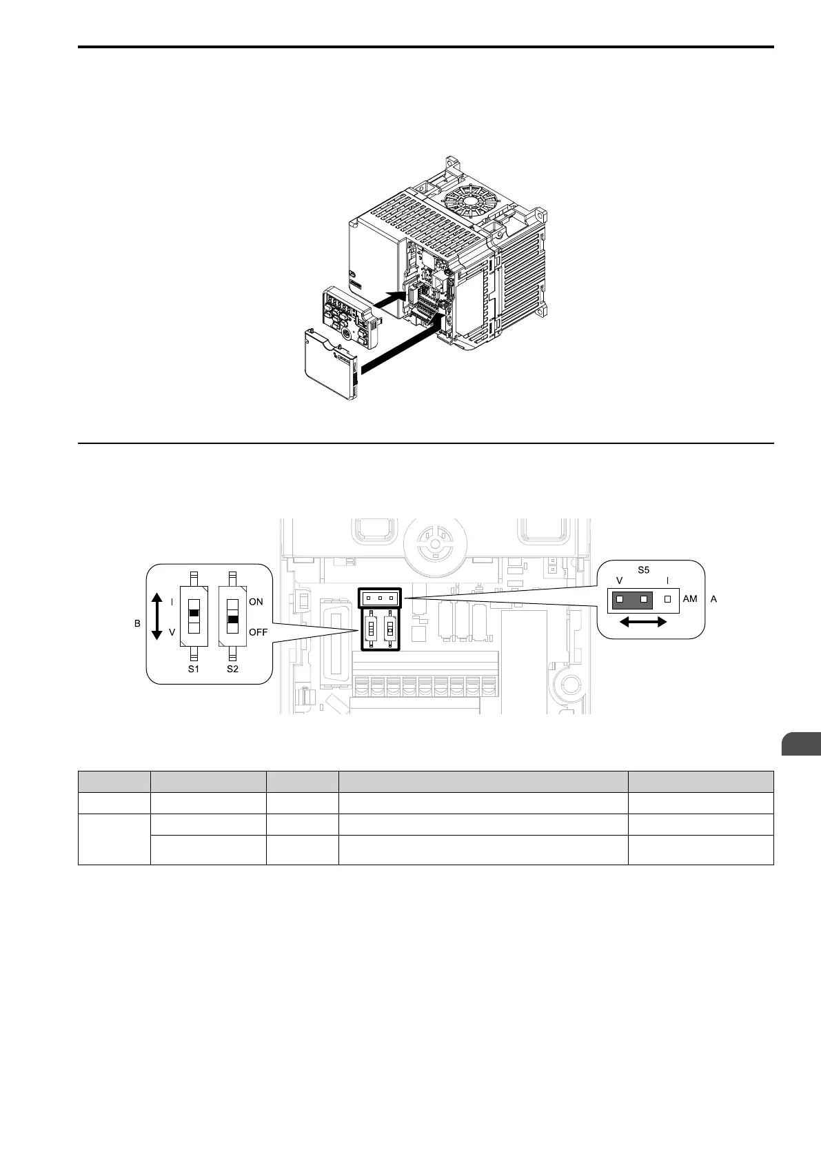
3. Install the front cover.
If you moved Jumper S5, attach the keypad before you attach the front cover.
If you did not move Jumper S5, attach the front cover.
Make sure that you do not pinch wires or signal lines between the front cover and the drive before you
reattach the cover.
Figure 3.44 Install the Front Cover
◆ Switches and Jumpers on the Terminal Board
The terminal board has switches to adapt the drive I/Os to the external control signals as shown in Figure 3.45.
Set the switches to select the functions for each terminal.
Figure 3.45 Locations of Switches
Table 3.13 I/O Terminals and Switches Functions
Position Switch Terminal Function Default
A Jumper switch S5 AM Sets the output method for terminal AM (voltage or current). V (voltage output)
B
DIP switch S1 A2 Sets the input method for terminal A2 (voltage or current). I (current input)
DIP switch S2 -
Enables and disables the MEMOBUS/Modbus communications
termination resistor.
OFF

 Loading...


