Troubleshooting
7
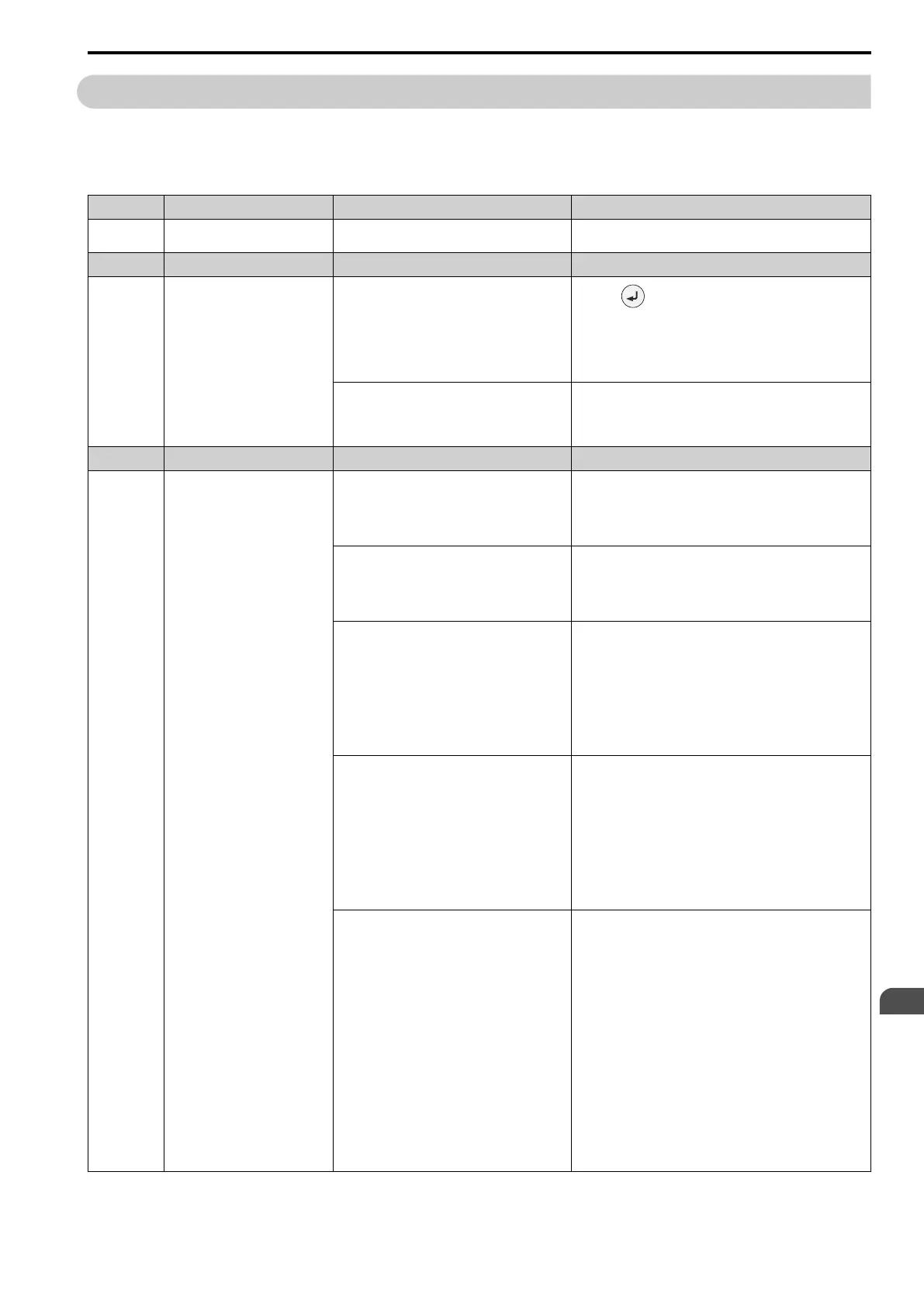
7.6 Parameter Setting Errors
YASKAWA SIEPC71061753C GA500 Technical Manual 287
7.6 Parameter Setting Errors
Parameter setting errors occur when multiple parameter settings do not agree, or when parameter setting values
are not correct. Refer to the table in this section, examine the parameter setting that caused the error, and remove
the cause of the error. You must first correct the parameter setting errors before you can operate the drive. The
drive will not send notification signals for the faults and alarms when these parameter setting errors occur.
Code Name Causes Possible Solutions
oPE01 Drive Capacity Setting Error
The value set in o2-04 [Drive Model (KVA)
Selection] does not agree with the drive model.
Set o2-04 to the correct value.
Code Name Causes Possible Solutions
oPE02 Parameter Range Setting Error
Parameter settings are not in the applicable setting
range.
1. Push to show U1-18 [oPE Fault Parameter], and find
parameters that are not in the applicable setting range.
2. Correct the parameter settings.
Note:
If more than one error occurs at the same time, other oPExx
errors have priority over oPE02.
Set E2-01 ≤ E2-03 [Motor Rated Current (FLA) ≤
Motor No-Load Current].
Make sure that E2-01 > E2-03.
Note:
If it is necessary to set E2-01 < E2-03, first lower the value
set in E2-03, and then set E2-01.
Code Name Causes Possible Solutions
oPE03 Multi-Function Input Setting Err
The settings for these parameters do not agree:
• H1-01 to H1-07 [Terminals S1 to S8 Function
Selection]
• H7-01 to H7-04 [Virtual Multi-Function Inputs 1
to 4]
Correct the parameter settings.
The settings for MFDIs overlap.
Note:
This does not include H1-xx = 20 to 2F [MFDI
Function Select = External Fault] and
[Reserved].
Set the parameters correctly to prevent MFDI function overlap.
You did not set these pairs of MFDI functions to
Digital Inputs (H1-xx and H7-01 to H7-04) at the
same time:
• Setting values 10 [Up Command] and 11 [Down
Command]
• Setting values 75 [Up 2 Command] and 76
[Down 2 Command]
• Setting values 42 [Run Command (2-Wire
Sequence 2)] and 43 [FWD/REV (2-Wire
Sequence 2)]
Set the MFDI pairs.
You set a minimum of two of these MFDI
combinations to Digital Inputs (H1-xx and H7-01 to
H7-04) at the same time:
• Setting values 10 [Up Command] and 11 [Down
Command]
• Setting values 75 [Up 2 Command] and 76
[Down 2 Command]
• Setting value A [Accel/Decel Ramp Hold]
• Setting value 1E [Reference Sample Hold]
• Setting values 44 to 46 [Add Offset Frequency 1
to 3 (d7-01 to d7-03)]
Remove the function settings that are not in use.
You set these commands in Digital Inputs (H1-xx
and H7-01 to H7-04) at the same time:
• Setting values 61 [Speed Search from Fmax] and
62 [Speed Search from Fref]
• Setting values 65, 66, 7A, 7B [KEB Ride-Thru 1
or 2 Activate] and 68 [High Slip Braking (HSB)
Activate]
• Setting values 16 [Motor 2 Selection] and 1A
[Accel/Decel Time Selection 2]
• Setting values 65, 66 [KEB Ride-Thru 1
Activate] and 7A, 7B [KEB Ride-Thru 2
Activate]
• Setting values 40, 41 [Forward RUN (2-Wire),
Reverse RUN (2-Wire)] and 42, 43 [Run
Command (2-Wire Sequence 2), FWD/REV (2-
Wire Sequence 2)]
• Setting values 60 [DC Injection Braking
Command] and 6A [Drive Enable]
• Setting values 16 [Motor 2 Selection] and 75, 76
[Up 2 Command, Down 2 Command]
Remove the function settings that are not in use.

 Loading...


