2.10 Conditions
50 YASKAWA SIEPC71061753C GA500 Technical Manual
◆ Thermal Compound
The thermal compound bonds the heating and cooling elements to each other and increases thermal transfer.
Apply the thermal compound between the heatsink plate and the mating surface. The applicable thermal
compound is different for different external heatsinks. When you select and apply a thermal compound, contact
the thermal compound manufacturer for additional information.
Table 2.24 shows an example of thermal compound selection.
Table 2.24 Example of Thermal Compound Selection
Manufacturer Type Model
Application Amount
(Thickness)
Shin-Etsu Chemical Co., Ltd. Oil-based compound X-23-7795 100 μm - 250 μm
*1
*1 The thickness can change with the condition of the metal surface.
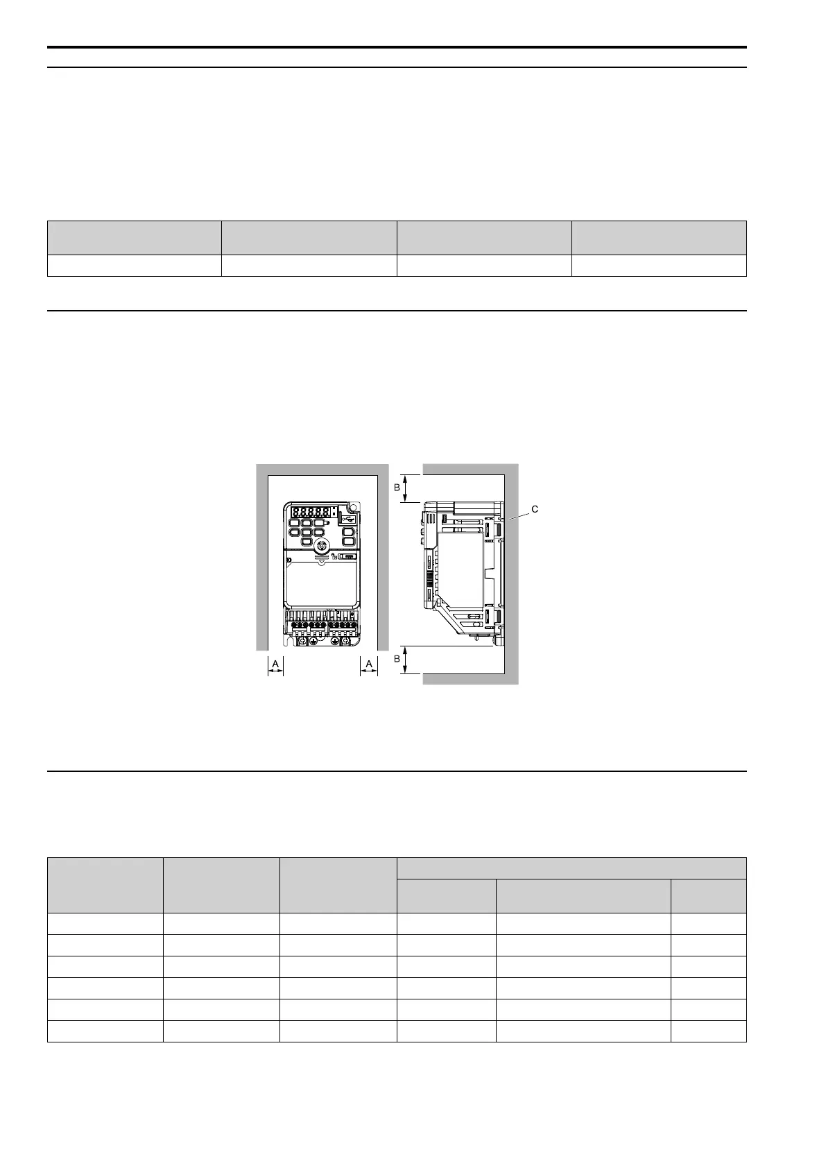
◆ Installation Position and Clearances
Use the clearances specified in Figure 2.15 to install the drive. Make sure that there is sufficient space for wiring
and airflow.
Tightly push the drive heatsink plate against the metal surface (enclosure panel) for correct thermal transfer
between the drive and the metal surface.
Note:
You cannot install finless-type drives side-by-side.
A - 30 mm (1.18 in) minimum
B - 100 mm (3.94 in) minimum
C - Metal surface (enclosure panel)
Figure 2.15 Installation Clearances
◆ Drive Watt Loss
■ Heavy Duty Rating (HD): Carrier Frequency = 2 kHz
Table 2.25 Single-Phase 200 V Class (Finless-Type Drive)
Drive Model
Rated Output Current
(A)
Carrier Frequency
(kHz)
Drive Watt Loss (W)
Interior Unit Loss
Heatsink Plate Loss
(P
Loss
)
Total Loss
B001 0.8 2 7 4 11
B002 1.6 2 10 7 17
B004 3 2 13 13 26
B006 5 2 17 23 40
B010 8 2 30 37 67
B012 11 2 40 48 88

 Loading...


