Startup Procedure and Test Run
4
4.11 Fine Tuning during Test Runs (Adjust the Control Function)
YASKAWA SIEPC71061753C GA500 Technical Manual 155
◆ Open Loop Vector Control for PM Motors
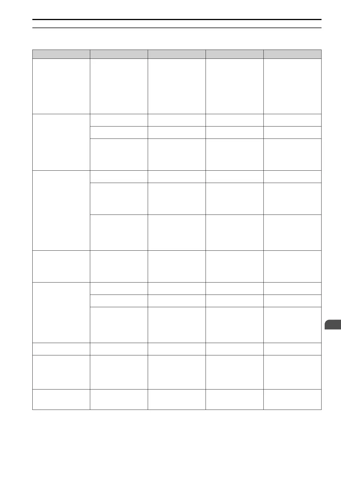
Table 4.20 Parameters for Fine Tuning the Drive (A1-02 = 5 [OLV/PM])
Issue Parameter Number Possible Solutions Default Recommended Setting
Unsatisfactory motor
performance
E1-xx parameters, E5-xx
parameters
• Check the settings for E1-06,
E1-04 [Base Frequency,
Maximum Output Frequency].
• Check the E5-xx and make
sure that you set all motor data
correctly.
Note:
Do not set E5-05 [PM Motor
Resistance (ohms/phase)] to a
line-to-line resistance value.
• Do Auto-Tuning.
- -
Unsatisfactory motor torque and
speed response
n8-55 [Motor to Load Inertia
Ratio]
Adjust to align the load inertia
ratio of the motor and machine.
0 Near the load inertia ratio.
n8-45 [Speed Feedback Detection
Gain]
Decrease the setting value in
increments of 0.05.
0.80 -
C4-01 [Torque Compensation
Gain]
Adjust the setting value.
Note:
If you set this value too high,
it can cause
overcompensation and motor
oscillation.
0.00 1.00
• Oscillation when the motor
starts.
• Motor stalls.
n8-51 [Pull-in Current @ Accel/
Decel]
Increase the setting value in
increments of 5%.
50% -
• b2-02 [DC Injection Braking
Current]
• b2-03 [DC Inject Braking
Time at Start]
Use DC Injection Braking at start.
Note:
This can cause the motor to
rotate in reverse for
approximately 1/8 of a turn at
start.
• b2-02: 50%
• b2-03: 0.00 s
• b2-02: Adjust as necessary.
• b2-03: 0.5 s
n8-55 [Motor to Load Inertia
Ratio]
Increase the setting value.
Note:
When you operate a single
motor or with a minimum
quantity of inertia, if you set
this value too high, it can
cause motor oscillation.
0 Near the load inertia ratio.
There is too much current during
deceleration.
n8-79 [Pull-in Current at
Deceleration]
Set n8-79 < n8-51.
50%
Note:
When n8-79 = 0, the drive
will apply the n8-51 setting to
the pull-in current during
deceleration.
Decrease in increments of 5%.
Stalling or oscillation occurs
when you apply the load during
constant speed
n8-47 [Pull-in Current Comp
Filter Time]
Decrease the setting value in
increments of 0.2 s.
5.0 s -
n8-48 [Pull-in/Light Load Id
Current]
Increase the setting value in
increments of 5%.
30% -
n8-55 [Motor to Load Inertia
Ratio]
Increase the setting value.
Note:
When you operate a single
motor or with a minimum
quantity of inertia, if you set
this value too high, it can
cause motor oscillation.
0 Near the load inertia ratio.
Hunting or oscillation
n8-45 [Speed Feedback Detection
Gain]
Increase the setting value in
increments of 0.05.
0.80 -
The drive detects STPo [Motor
Step-Out Detected] fault when
the load is not too high.
• E5-09 [PM Back-EMF Vpeak
(mV/(rad/s))]
• E5-24 [PM Back-EMF L-L
Vrms (mV/rpm)]
• Adjust the setting value.
• Examine the motor code on
the motor nameplate or the
data sheet, then set correct
values for E5-09 or E5-24.
*1
• Yaskawa motor
Set the motor code from the
motor nameplate.
• Motor from another
manufacturer
Set the values from the test
report.
The drive detected stalling or
STPo [Motor Step-Out Detected]
at high speed and maximum
output voltage.
n8-62 [Output Voltage Limit
Level]
Set to a value lower than the
actual input voltage.
• 200.0 V
• 400.0 V
-
*1 The default setting changes when the settings for E5-01 [Motor Code Selection] and o2-04 [Drive Model (KVA) Selection] change.

 Loading...


