Network Communications
6
6.3 MEMOBUS/Modbus Communications
YASKAWA SIEPC71061753C GA500 Technical Manual 229
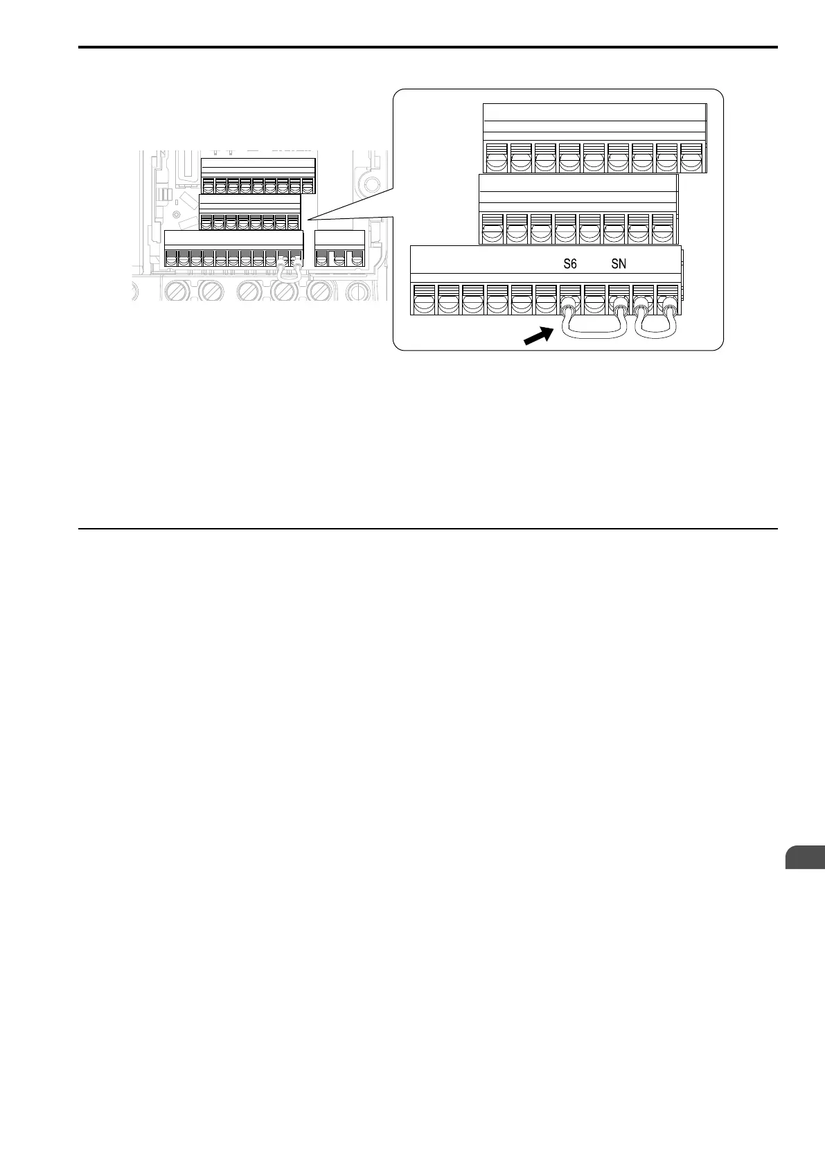
4. Connect a jumper between control circuit terminals S6 and SN.
Figure 6.8 Self-Diagnostics Jumper Terminals
5. Energize the drive.
6. When normal, the keypad will show PASS [MEMOBUS/Modbus Communications Test Mode Normal].
When there is an error, the keypad will show CE [MEMOBUS/Modbus Communications Error].
7. De-energize the drive.
8. Disconnect the wire jumper between terminals S6 and SN. Set terminal S6 to its initial function.
Self-Diagnostics is complete and the drive returns to its usual function.
◆ Communications Data Table
The communication data types are command data, monitor data, and broadcast message. Command Data on page
229, Monitor Data on page 231, and Broadcast Messages on page 242 show the communications data.
Refer to the Parameter List for parameter communications registers.
■ Command Data
You can read and write command data.
Note:
Set the reserved bit to 0. Do not write the data in the reserved register or the monitor register.

 Loading...


