Parameter Details
12
12.8 H: Terminal Function Selection
YASKAWA SIEPC71061753C GA500 Technical Manual 673
• If you use this function to set the analog input value as the master frequency reference, set b1-01 = 1
[Frequency Reference Selection 1 = Analog Input]. This setting value is the default value for terminals A1 and
A2.
• The frequency reference is the sum of the input values for terminals A1 and A2 when they are used at the same
time. For example, when a 20% bias is input to terminal A2 while a frequency reference of 50% is input from
terminal A1, the calculated frequency reference will be 70% of the maximum output frequency.
■ 1: Frequency Gain
Setting Value Function Description
1 Frequency Gain
The drive multiplies the analog frequency reference with the input value from the MFAI set with this function.
Example: When you set frequency gain for terminal A2
• H3-10 = 1 [Terminal A2 Function Selection = Frequency Gain]
• A 50% frequency gain is input to terminal A2
• A frequency reference of 80% is input from terminal A1
The calculated frequency reference is 40% of the maximum output frequency.
■ 2: Auxiliary Frequency Reference 1
Setting Value Function Description
2 Auxiliary Frequency
Reference 1
Sets Reference 2 through multi-step speed reference to enable the command reference (Auxiliary Frequency Reference 1) from
the analog input terminal set here. This value is a percentage where the Maximum Output Frequency setting is a setting value of
100%.
■ 3: Auxiliary Frequency Reference 2
Setting Value Function Description
3 Auxiliary Frequency
Reference 2
Sets Reference 3 through multi-step speed reference to enable the command reference (Auxiliary Frequency Reference 2) from
the analog input terminal set here. This value is a percentage where the Maximum Output Frequency setting is a setting value of
100%.
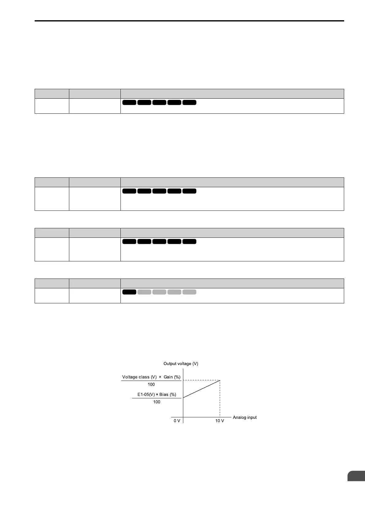
■ 4: Output Voltage Bias
Setting Value Function Description
4 Output Voltage Bias
Set this parameter to input a bias signal to amplify the output voltage.
The gain (%) for the MFAI terminals A1 and A2 is 100% of the voltage class standard, which is 200 V for 200 V
class drives and 400 V for 400 V class drives. The bias (%) for MFAI terminals A1 and A2 is 100% of the voltage
configured for E1-05 [Maximum Output Voltage].
Note:
The gain for each terminal A1 and A2 is set independently with H3-03 [Terminal A1 Gain Setting] and H3-11 [Terminal A2 Gain
Setting]. The bias for each terminal A1 and A2 is set independently with H3-04 [Terminal A1 Bias Setting] and H3-12 [Terminal A2
Bias Setting].
Figure 12.92 Output Voltage Bias through Analog Input

 Loading...


