128 / 184
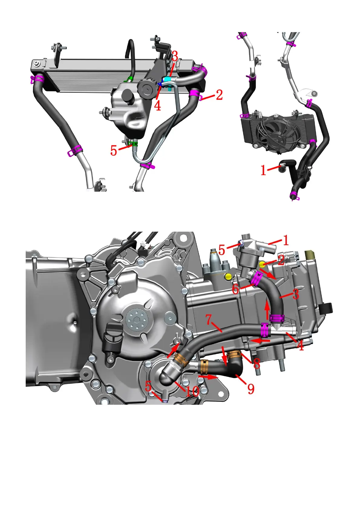
Coolant system hoop/clamp distribution map
1-Water pipe clamp (φ26) 2-Water pipe clamp (φ22)*10 3-Water pipe clamp (φ26) 4-Water pipe clamp (φ9) 5-Water
pipe clamp (φ10.5)*2
Thermostat assembly and small loop
1- Thermostat assembly 2-M6×22 bolt*2 3-Small circulating water pipe 4-Tee pipe 5-M6×12 bolt*2
6-Water pipe hoop (φ22)*3 7-Water pump cover inlet pipe 8-Water pipe hoop (φ24)*3 9-Cylinder inlet pipe 10-Water
pump cover assembly
Caution: The bolt (5) at the thermostat is an exhaust bolt, and the bolt at the water pump cover is a bolt for cooling
liquid. There are O-rings of φ5.6×φ1 at both locations, which need to be replaced once they are disassembled.
a. Use the hoop pliers to remove the hoop ⑹ and hoop ⑻ in the direction of the arrow respectively, and separate
the water pipes ⑶, ⑺ and ⑼ and the three-way pipe. Remove the hoop from the water pipe.
 Loading...