Actual signals and parameters 195
1103 REF1 SELECT Selects the signal source for external reference REF1. See
section Block diagram: Reference source for EXT1 on page
128.
AI1
KEYPAD Control panel 0
AI1 Analog input AI1 1
AI2 Analog input AI2 2
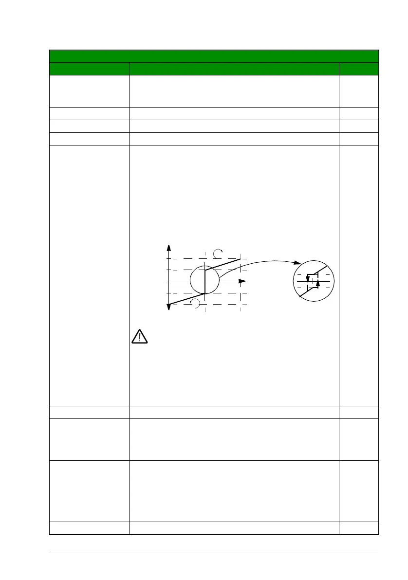
AI1/JOYST Analog input AI1 as joystick. The minimum input signal runs
the motor at the maximum reference in the reverse
direction, the maximum input at the maximum reference in
the forward direction. Minimum and maximum references
are defined by parameters 1104 REF1 MIN and 110 5 REF1
MAX.
Note: Parameter 1003 DIRECTION must be set to
REQUEST.
WARNING! If parameter 1301 MINIMUM AI1 is set to
0 V and analog input signal is lost (ie, 0 V), the
rotation of the motor is reversed to the maximum reference.
Set the following parameters to activate a fault when analog
input signal is lost:
Set parameter 1301 MINIMUM AI1 to 20% (2 V or 4 mA).
Set parameter 3021 AI1 FAULT LIMIT to 5% or higher.
Set parameter 3001 AI<MIN FUNCTION to FAULT.
3
AI2/JOYST See selection AI1/JOYST.4
DI3U,4D(R) Digital input DI3: Reference increase. Digital input DI4:
Reference decrease. Stop command resets the reference to
zero. Parameter 2205 ACCELER TIME 2 defines the rate of
the reference change.
5
DI3U,4D Digital input DI3: Reference increase. Digital input DI4:
Reference decrease. The program stores the active speed
reference (not reset by a stop command). When the drive is
restarted, the motor ramps up at the selected acceleration
rate to the stored reference. Parameter 2205 ACCELER
TIME 2 defines the rate of the reference change.
6
COMM Fieldbus reference REF1 8
All parameters
No. Name/Value Description Def/FbEq
1104
-11 04
-11 05
1105
par. 1301 = 20%, par 1302 = 100%
+2%-2%
0
Speed ref
(REF1)
AI1
1104
-1104
2 V / 4 mA 10 V / 20 mA 6
Hysteresis 4%
of full scale

 Loading...


