216 Actual signals and parameters
1803 FILTER FREQ
IN
Defines the filter time constant for frequency input, ie, the
time within which 63% of a step change is reached. See
section Frequency input on page 135.
0.1 s
0.0…10.0 s Filter time constant 1 = 0.1 s
1804 TO MODE Selects the operation mode for the transistor output TO.
See section Transistor output on page 136.
DIGITAL
DIGITAL Transistor output is used as a digital output DO. 0
FREQUENCY Transistor output is used as a frequency output FO. 1
1805 DO SIGNAL Selects a drive status indicated through digital output DO. FAULT(-1)
See parameter 1401 RELAY OUTPUT 1.
1806 DO ON DELAY Defines the operation delay for digital output DO. 0.0 s
0.0…3600.0 s Delay time 1 = 0.1 s
1807 DO OFF
DELAY
Defines the release delay for digital output DO. 0.0 s
0.0…3600.0 s Delay time 1 = 0.1 s
1808 FO CONTENT
SEL
Selects a drive signal to be connected to frequency output
FO.
104
x…x Parameter index in group 01 OPERATING DATA. For
example, 102 = 0102 SPEED.
1 = 1
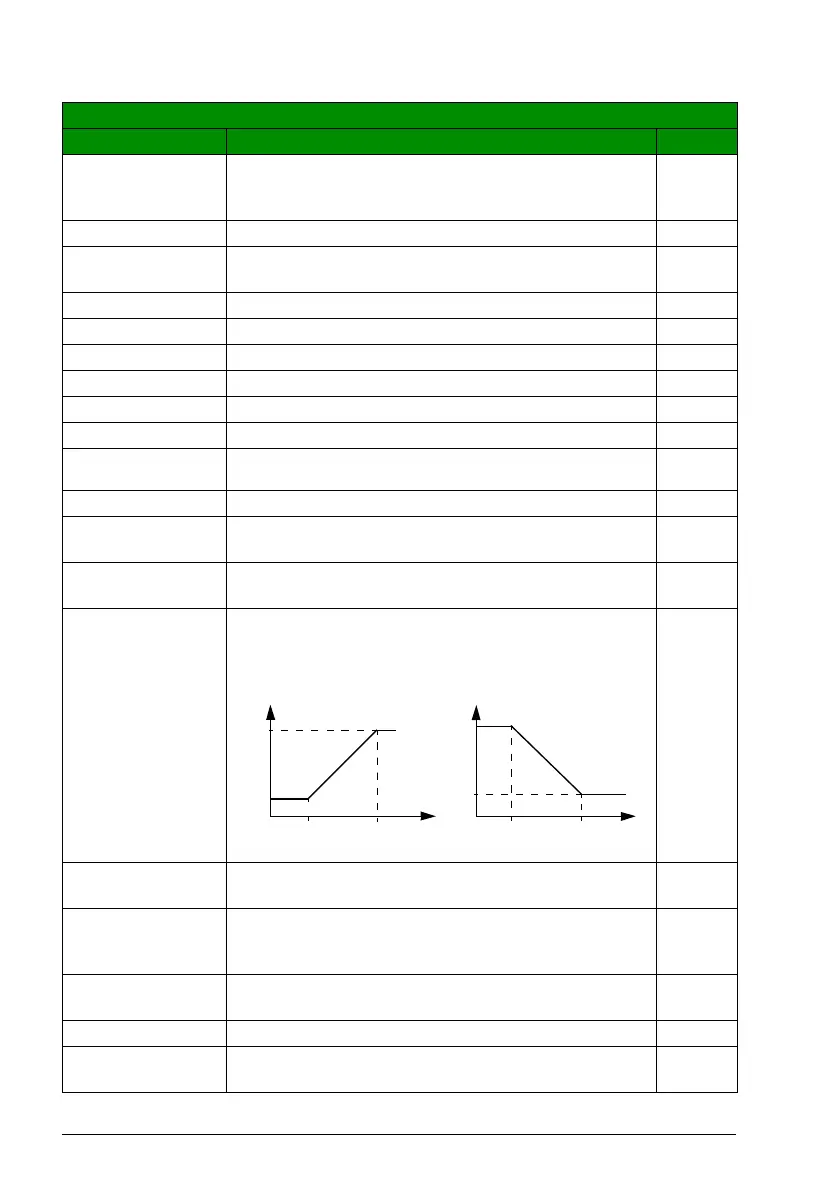
1809 FO CONTENT
MIN
Defines the minimum frequency output FO signal value.
Signal is selected with parameter 1808 FO CONTENT SEL.
FO minimum and maximum correspond to 1811 MINIMUM
FO and 1812 MAXIMUM FO settings as follows:
-
x…x Setting range depends on parameter 1808 FO CONTENT
SEL setting.
-
1810 FO CONTENT
MAX
Defines the maximum frequency output FO signal value.
Signal is selected with parameter 1808 FO CONTENT SEL.
See parameter 1809 FO CONTENT MIN.
-
x…x Setting range depends on parameter 1808 FO CONTENT
SEL setting.
-
1811 MINIMUM FO Defines the minimum value for frequency output FO. 10 Hz
10…16000 Hz Minimum frequency. See parameter 1809 FO CONTENT
MIN.
1 = 1 Hz
All parameters
No. Name/Value Description Def/FbEq
1812
1811
1809 1810
1812
1811
1809 1810
FO
content
FO
FO
FO
content

 Loading...


