244 Actual signals and parameters
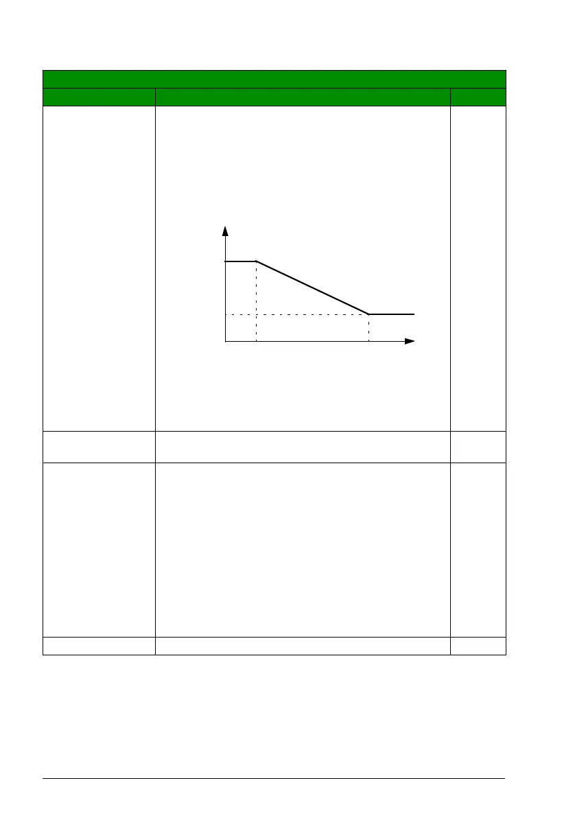
ON (LOAD) The drive is started with 4 kHz switching frequency to gain
maximum output during the start. After start-up, the
switching frequency is controlled towards the selected value
(parameter 2607 SWITCH FREQ CTRL) if the output
current or the temperature allows.
This selection provides adaptive switching frequency
control. Adaptation decreases the output performance in
some cases.
2
LONG CABLE Fixes switching frequency to 4 kHz and prolongs the
minimum pulse time enabling the use of longer cables.
3
2608 SLIP COMP
RATIO
Defines the slip gain for the motor slip compensation
control. 100% means full slip compensation, 0% means no
slip compensation. Other values can be used if a static
speed error is detected despite the full slip compensation.
Can be used only in scalar control (ie, when parameter 9904
MOTOR CTRL MODE setting is SCALAR: FREQ).
Example: 35 Hz constant speed reference is given to the
drive. Despite the full slip compensation (SLIP COMP
RATIO = 100%), a manual tachometer measurement from
the motor axis gives a speed value of 34 Hz. The static
speed error is 35 Hz - 34 Hz = 1 Hz. To compensate the
error, the slip gain should be increased.
0%
0…200% Slip gain 1 = 1%
All parameters
No. Name/Value Description Def/FbEq
* Temperature depends on the drive output frequency.
** Short term overloading is allowed with each switching
frequency depending on actual loading.
16 kHz
4kHz
Drive current I
2N
Drive
temperature
f
sw
limit
80…100 °C * 100…120 °C *
T
50% ** 100% **

 Loading...


