AI1 and AI2 as Pt100, Pt1000, Ni1000, KTY83 and KTY84 sensor inputs
WARNING!
IEC 61800-5-1 requires double or reinforced insulation between live parts and
accessible parts when:
• the accessible parts are not conductive, or
• the accessible parts are conductive, but not connected to the protective earth.
Obey this requirement when you plan the connection of the motor temperature
sensor to the drive.
If the motor temperature sensor has a reinforced insulation vs. the motor windings, you
can connect it directly to the drive IO interface. This section shows the connection. If
the sensor has no reinforced insulation, you must use another type of connection to
fulfill the safety requirements. See Implementing a motor temperature sensor
connection (page 61).
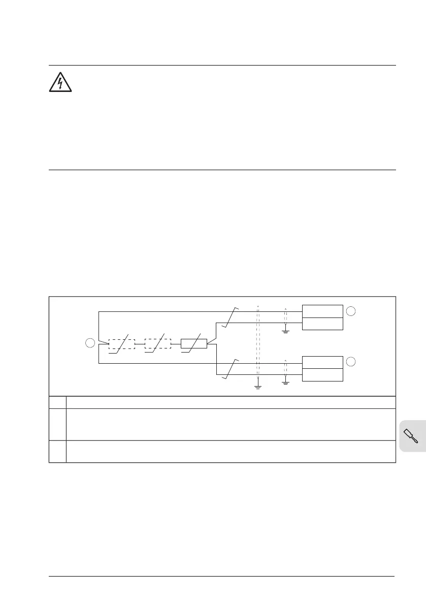
You can connect temperature measurement sensors (one, two or three Pt100 sensors;
one, two or three Pt1000 sensors; or one Ni1000, KTY83 or KTY84) between an analog
input and output as shown below. Leave the sensor end of the cable shield unconnected.
See the firmware manual for information on the related Motor thermal protection function.
1…3 × (Pt100 or Pt1000) or 1 × (Ni1000 or KTY83 or KTY84)1
Analog input. Set the analog input type to V (volt) in parameter group 12 Standard AI. Define
the temperature sensor type, signal source, etc. with parameters 35.11…35.24. Set the
analog input type to V (volt) in parameter group 12 Standard AI.
2
Analog output. Select the Excitation mode for the analog output in parameter group
13 Standard AO.
3
Safe torque off
For the drive to start, both STO connections (S+ to S1 and S+ to S2) must be closed.
By default, the terminal block has jumpers to close the circuit. Remove the jumpers
before connecting external Safe torque off circuitry to the drive. See chapter The Safe
torque off function.
Electrical installation – North America 109

 Loading...


