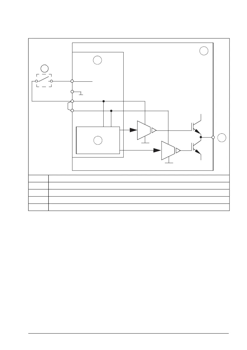
Single-channel connection of activation switch
S+
+ 24 V DC
S1
S2
SGND
UDC+
UDC-
A
K
1
2
3
4
Drive1
Control unit2
Control logic3
To motor4
Activation switchK
Note:
• Both STO inputs (S1, S2) must be connected to the activation switch. Otherwise,
no SIL/PL classification is given.
• Pay special attention to avoiding any potential failure modes for the wiring. For
example, use a shielded cable. For measures for fault exclusion of wiring, refer to
EN ISO 13849-2:2012, table D.4.
The Safe torque off function 187
 Loading...


