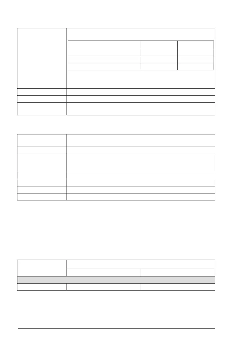
Use an input choke, if the short-circuit capacity of the network at the drive
terminals is more than specified in this table:
Input choke
R3, R4R0, R1, R2Input voltage
->1.5 kA1-phase 200 … 240 V
>7.5 kA>5.0 kA3-phase 200 … 240 V
>10 kA>5.0 kA3-phase 380 … 480 V
You can use one choke for several drives if the short-circuit capacity at
the drive terminals is decreased to the value in the table.
47 … 63 Hz, maximum rate of change 2%/sFrequency (f1)
Max. ±3% of nominal phase to phase input voltageImbalance
0.98 (at nominal load)Fundamental power
factor (cos phi)
Motor connection data
Asynchronous AC induction motors, permanent magnet synchronous
motors or ABB synchronous reluctance motors (SynRM motors)
Motor type
0 … U1, 3-phase symmetricalVoltage (U2)
The motor output is short-circuit proof by IEC 61800-5-1 and UL 61800-
5-1.
Short-circuit protec-
tion (IEC 61800-5-1,
UL 61800-5-1)
0 … 599 HzFrequency (f2)
0.01 HzFrequency resolution
See the electrical ratings given in this manual.Current
2, 4, 8, or 12 kHzSwitching frequency
■ Motor cable length
Operational functionality and motor cable length
The drive is designed to operate with optimum performance with these maximum motor
cable lengths. The values are valid for 4 kHz switching frequency.
Note: Conducted and radiated emissions of these motor cable lengths do not comply
with the EMC requirements of IEC/EN 61800-3.
Maximum motor cable lengthFrame
ftm
Standard drive, without external options
328100R0…R4
Note: In multimotor systems, the calculated sum of all motor cable lengths must not
exceed the maximum motor cable length given in the table.
152 Technical data
 Loading...


