1000 V DC,
> 100 Mohm
U1-PE, V1-PE, W1-PE
ohm
M
3~
U1
V1
W1
PE
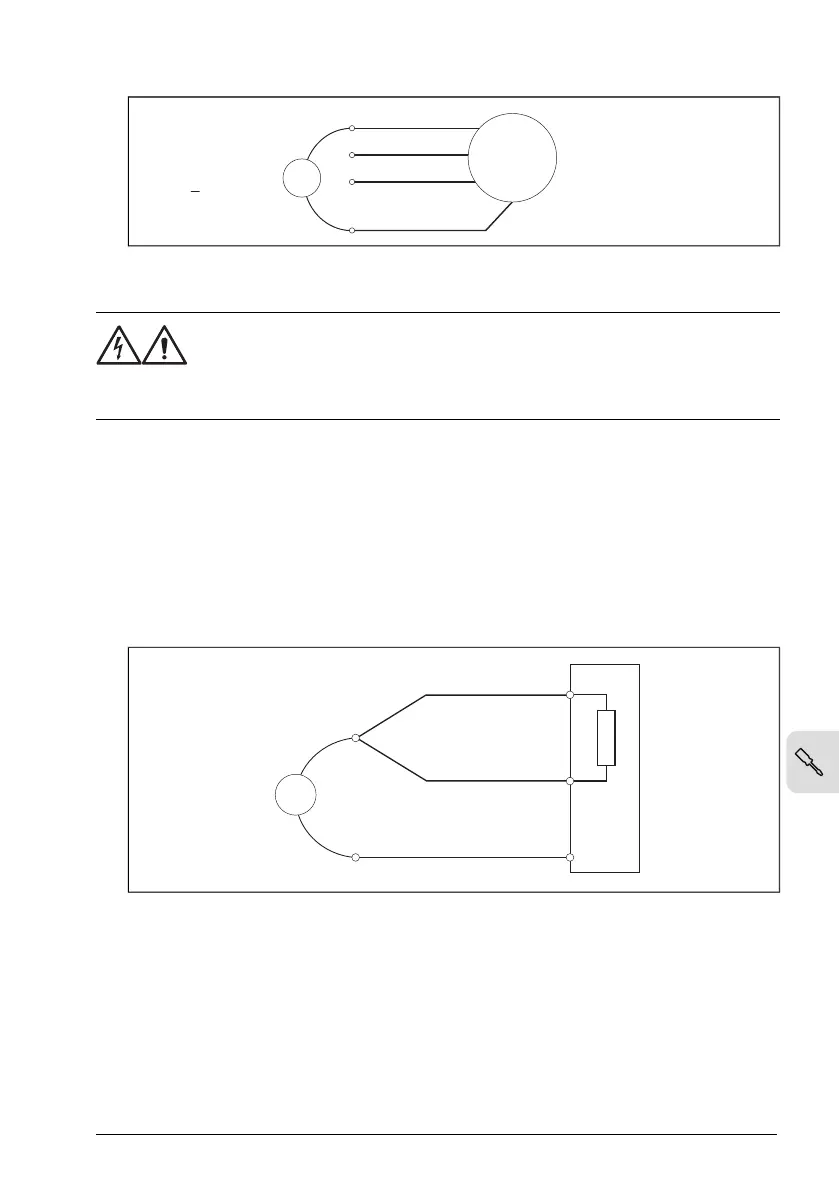
■ Measuring the insulation resistance of the brake resistor circuit
WARNING!
Obey the safety instructions of the drive. If you ignore them, injury or death,
or damage to the equipment can occur. If you are not a qualified electrical
professional, do not do installation or maintenance work.
1.
Stop the drive and do the steps in section Electrical safety precautions (page 17)
before you start the work.
2. Make sure that the resistor cable is connected to the resistor and disconnected from
the drive output terminals.
3. At the drive end, connect the R+ and R- conductors of the resistor cable together.
Measure the insulation resistance between the conductors and the PE conductor
with a measuring voltage of 1000 V DC. The insulation resistance must be more
than 1 Mohm.
R-
R+
ohm
PE
1000 V DC,
> 1 Mohm
Grounding system compatibility check – IEC
■ EMC filter
Some drive types have an internal EMC filter as standard. You can install a drive that
has the internal EMC filter connected to a symmetrically grounded TN-S system
(center-grounded wye). For other systems, refer to Compatibility of EMC filter and
ground-to-phase varistor with the grounding system (page 68).
Electrical installation – IEC 67
 Loading...


