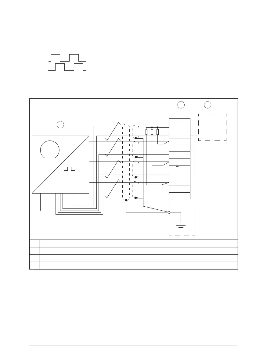
Wiring diagrams – Open collector (sinking) encoder output
Diagram assumes normal pulse order in Forward rotation: Pulse A leads.
For encoders with pulse B leading, change the diagram: Wire encoder A and B to BTAC
terminals B and A, respectively.
1)
2 3
V
in
V
out
GND
A
A
GND
B
B
GND
Z
GND
Z
1
0
0V V
CC
2
SCR
1
2)
R
L
Encoder1
BTAC module2
Encoder power supply3
Three identical resistors4
The resistor size depends on the encoder power supply V
in
= V
OUT
:
R
L
= 2.7…3.0 kohm, 0.5 WV
in
= 30 V
R
L
= 1.8…2.2 kohm, 0.5 WV
in
= 24 V
R
L
= 1.0…1.5 kohm, 0.5 WV
in
= 15 V
R
L
= 390…470 kohm, 0.125 WV
in
= 5 V
BTAC-02 pulse encoder interface module 213
 Loading...


