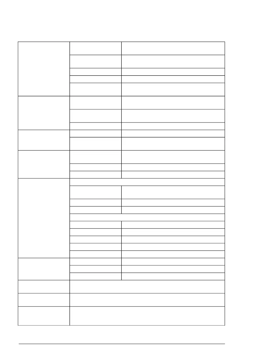
Control connection data
0 … 10 V DC (10% overrange, 11 V DC max.)Voltage signal, single-
ended
Analog inputs (AI1,
AI2)
R
in
= 221.6 kohm
0 … 20 mA (10% overrange, 22 mA max.)Current signal, single-
ended
R
in
= 137 ohm
≤ 1.0%, of full scaleInaccuracy
up to 30 V DCOvervoltage protection
10 V DC ±1%, max. load current 10 mAPotentiometer refer-
ence value
0 … 20 mA (10% overrange, 22 mA max.) into
500 ohm load
Current output modeAnalog output (AO)
0 … 10 V DC (10% overrange, 11 V DC max.)
into 200 kohm minimum load (resistive)
Voltage output mode
≤ 1.0%, of full scaleInaccuracy
+24 V DC ±10%, max. 250 mAAs outputAuxiliary voltage out-
put/optional input
(+24V)
+24 V DC ±10%, max. 1000 mA (incl internal
fan load)
As input (optional)
12 … 24 V DC (int. or ext. supply) Max. 30 V
DC.
VoltageDigital inputs
(DI1…DI5)
PNP and NPNType
R
in
= 2 kohm
Input impedance
As inputsProgrammable digital
I/O (DIO1, DIO2)
12 … 24 V DC with internal or external supply.
Max. 30 V DC.
Voltage
PNP and NPNType
R
in
= 2 kohm
Input impedance
As outputs
Transistor output PNPType
30 V DCMax. switching voltage
70 mA / 30 DC, short-circuit protectedMax. switching current
10 Hz … 16 kHzFrequency
1 HzResolution
1 From C (NO + NC)TypeRelay output (RA, RB,
RC)
250 V AC / 30 V DCMax. switching voltage
2 AMax. switching current
10 Hz … 16 kHzFrequency input (FI)
DI3 and DI4 can be used as digital or frequency inputs.
DIO1 and DIO2 can be used as digital or frequency outputs.Frequency output
(FO)
Refer to The Safe torque off function (page 183)
Safe torque off (STO)
interface (SGND, S+,
S1, S2)
154 Technical data
 Loading...


