clockwise, in most encoders channel A leads channel B. To determine the leading
channel, refer to the encoder documentation or use an oscilloscope.
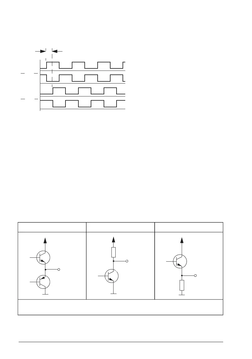
The diagram shows normal phasing:
Pulse A leads (rises earlier than) pulse
B.
90°
A or 1
A
or 1
B or 2
B
or 2
Connect the encoder output channel that leads when the drive runs Forward to BTAC
terminal A. Connect the output channel that trails to BTAC terminal B.
Option B: Functional test
For this test:
•
Temporarily, switch the drive to the scalar mode. Set parameter 99.04 Motor ctrl
mode to 1 (SCALAR).
• Run the drive in the forward direction.
•
Make sure that the value of parameter 90.13 Enc1 revol extension increases.
•
If the value of parameter 90.13 Enc1 revol extension decreases, switch the A+/A-
(or 1+/1-) connections.
Encoder output types
Open emitter (sourcing)Open collector (sinking)Push-pull
V
CC
= Encoder input power supply voltage
R
L
= Load resistor at encoder output channel
210 BTAC-02 pulse encoder interface module
 Loading...


