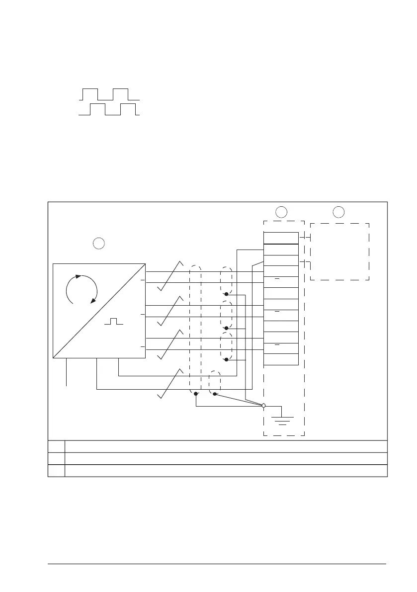
Wiring diagrams – Push-pull type encoder output
Diagram assumes normal pulse order in Forward rotation: Pulse A leads
For encoders with pulse B leading, change the diagram:
• Wire encoder A and B to BTAC terminals B and A, respectively.
• Wire encoder A- and B- (if present) to BTAC terminals B- and A-, respectively.
Differential connection
1)
1
1
0
0V
V
CC
2
2
0
SCR
1
2 3
V
in
V
out
GND
A
A
GND
B
B
GND
Z
Z
GND
Encoder1
BTAC module2
Encoder power supply3
BTAC-02 pulse encoder interface module 211
 Loading...


