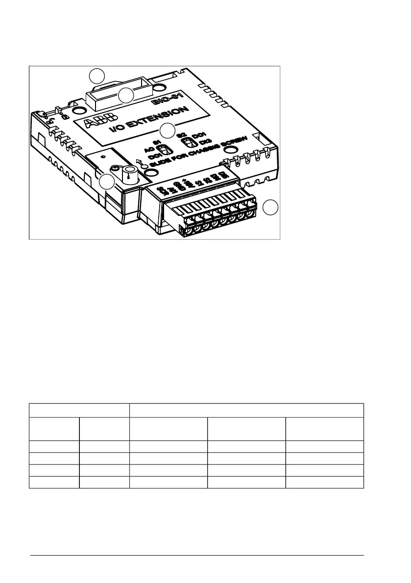
■ Layout
1. Locking tab
2. Option module slot
3. Chassis screw
4. I/O connector
5. Switches for configur-
ing terminals S1 and S2
Mechanical installation
See the electrical installation instructions of the drive.
Before you install the BIO-01 option module, make sure that the chassis screw slider
is in the top position. After the option module is installed, tighten the chassis screw and
move the slider to the bottom position.
The BIO-01 option module kit comes with a higher cable clamp plate. Use this cable
clamp plate to ground the wires that connect to the BIO-01 option module.
Terminal configuration
You must configure terminals S1 and S2 before you install the fieldbus module. Refer
to the table that follows for the possible configurations:
ResultSetting
Supported configur-
ation
Terminal S2 func-
tions as
Terminal S1 func-
tions as
Switch S2Switch S1
YesDigital input DI3Digital output DO1DI3 (default)DO1 (default)
YesDigital input DI3Analog output AO1DI3 (default)AO1
YesDigital output DO1Analog output AO1DO1AO1
No--DO1DO1 (default)
If you change the switch configuration while the drive is powered on, the drive will trip
on a fault. Also, an unsupported configuration will cause the drive to trip on a fault.
232 BIO-01 I/O extension module
 Loading...


