Electrical installation
The BIO-01 module has removable spring clamp terminals. Use ferrules on the
multistranded conductor ends.
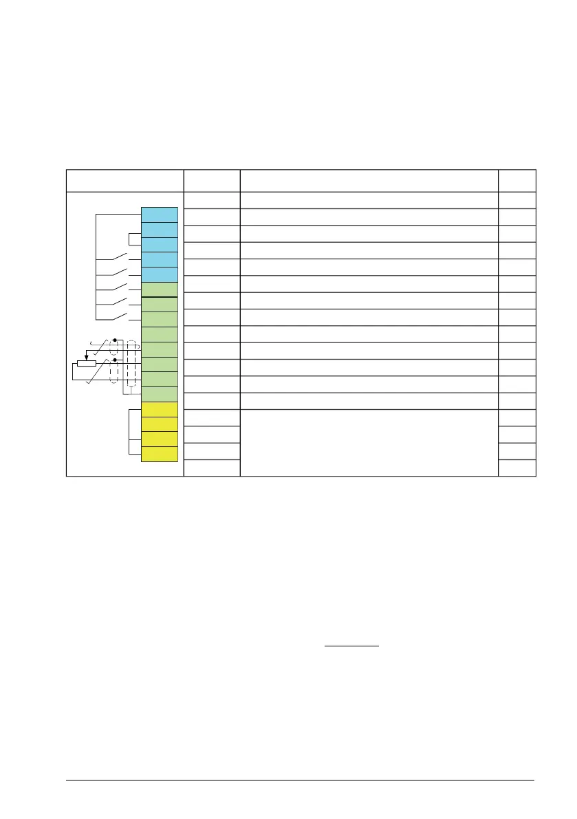
The connection diagram below is applicable to drives with the BIO-01 I/O extension
module when the ABB standard macro is selected (parameter 96.04).
1)
DescriptionTerminal
Connection
×Auxiliary voltage output +24 V DC, max. 250 mA+24 V
S+
SGND
S1
S2
+24 V
DGND
DCOM
DI1
DI2
+24 V
DGND
DCOM
DI1
DI2
AI1
+10V
GND
SCR
DI3
DI4
DI5
DO1
×Auxiliary voltage output commonDGND
×Digital input common for allDCOM
×Stop (0) / Start (1)DI1
×Forward (0) / Reverse (1)DI2
Constant frequency/speed selectionS2 (DI3)
Constant frequency/speed selectionDI4
Ramp set 1 (0) / Ramp set 2 (1)DI5
Not configured (DIO1)S1 (DO1)
Output frequency/speed ref: 0 … 10 V DCAI1
Reference voltage +10 V DC (max. 10 mA)+10V
Analog circuit common / DO commonGND
Signal cable shieldSCR
×Safe torque off. Both S1 and S2 circuits must be
closed for the drive to start. (Factory connection.)
S+
×SGND
×S1
×S2
1)
× = on base unit, blank = on BIO-01 module.
Start-up
The BIO-01 module is automatically identified by the drive firmware. To configure the
inputs and outputs, refer to the drive firmware manual.
Technical data
Control connection data: Spring type terminal blocks. Conductor size accepted by
the terminals: 0.2 … 1.5 mm
2
(24 … 16 AWG). Exception: max. 0.75 mm
2
(18 AWG)
for a multistranded conductor with a ferrule and plastic sleeve.
BIO-01 I/O extension module 233
 Loading...


