■ Layout
1. BREL-01 module
172 BREL-01 relay output extension module
Hardware description
Product overview
BREL-01 relay output extension module (option +L511) adds four relay outputs to the
drive.
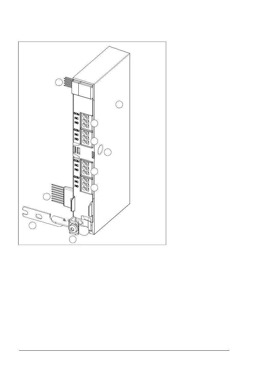
Layout
1. BREL module
2. Locking screw hole
3. X103 connector
4. X104 connector
5. X105 connector
6. X106 connector
7. Internal X100 connector
8. Internal X102 connector
9. Grounding rail
10. Grounding screw
8
1
2
3
4
5
6
7
9
10
2. Locking screw hole
3. X103 connector
4. X104 connector
5. X105 connector
6. X106 connector
7. Internal X100 connector
8. Internal X102 connector
9. Grounding rail
10. Grounding screw
Mechanical installation
See the electrical installation instructions of the drive.
Electrical installation
Use 0.5 … 2.5 mm
2
(20 … 14 AWG) cable with a sufficient voltage rating.
If you connect an inductive load (relay or contactor coil, motor) protect the relay contacts
with a varistor, RC filter (AC) or diode (DC). Install the protective component as close
to the inductive load as possible. Do not install protective components at the relay output
terminals.
222 BREL-01 relay output extension module
 Loading...


