working. Continue only if you are an electrical professional certified for the work.
Obey the local regulations. If you ignore them, injury or death can occur.
To identify the grounding system, examine the supply transformer connection. See the
applicable electrical diagrams of the building. If that is not possible, measure these
voltages at the distribution board, and use the table to define the grounding system
type.
1. input voltage line to line (U
L-L
)
2. input voltage line 1 to ground (U
L1-G
)
3. input voltage line 2 to ground (U
L2-G
)
4. input voltage line 3 to ground (U
L3-G
).
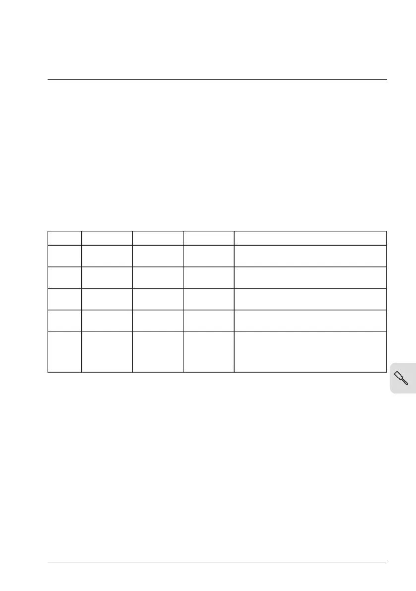
The table below shows the line-to-ground voltages in relation to the line-to-line voltage
for each grounding system.
Electrical power system typeU
L3-G
U
L2-G
U
L1-G
U
L-L
Symmetrically grounded TN system (TN-S
system)
0.58·X0.58·X0.58·XX
Corner-grounded delta system (nonsymmet-
rical)
01.0·X1.0·XX
Midpoint-grounded delta system (nonsym-
metrical)
0.5·X0.5·X0.866·XX
IT systems (ungrounded or high-resistance-
grounded [>30 ohms]) nonsymmetrical
Varying level
versus time
Varying level
versus time
Varying level
versus time
X
TT system (the protective earth connection
for the consumer is provided by a local
earth electrode, and there is another inde-
pendently installed at the generator)
Varying level
versus time
Varying level
versus time
Varying level
versus time
X
Electrical installation – IEC 71
 Loading...


