9. Communicator Touch Panel
5
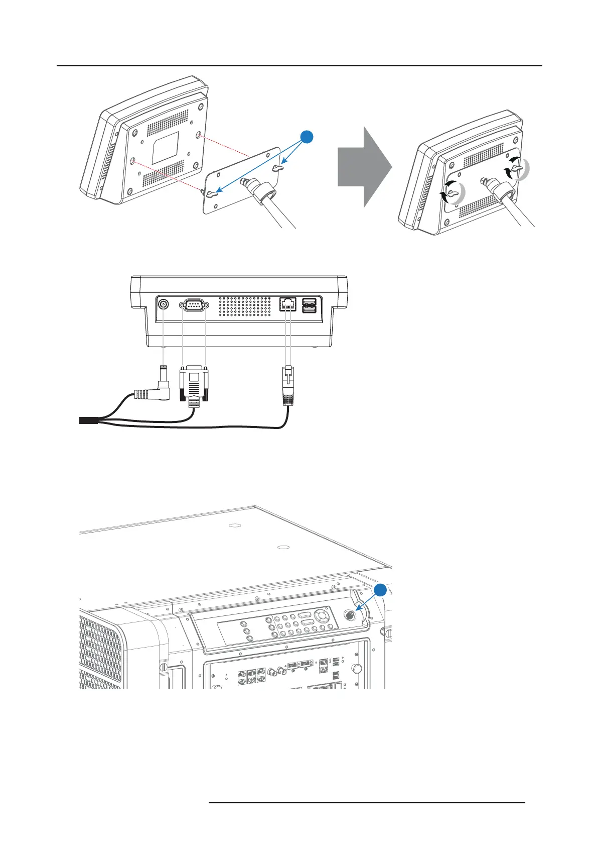
Image 9-6
4. Connect the DC plug, the RJ45 Ethernet plug and the D-SUB plug of the customized cable into t
heir respective sockets on the
Touch Panel interface.
Image 9-7
5. Remove the right side cover. See "Removal of the right side cover", pa ge 125.
6. Connect the circular plug of the customized cable with the circular socket (6) a t the right side of the Local Key pad of the projector.
Caution: To avoid connector damage, align the pins before you c onnect the customized cable.
Note: Ensure to tighten the locking nut on the connector.
6
Image 9-8
7. Attach the multi cable t o the swivel arm using the two Velcro strips.
8. Position the Touch Panel interface in the desired loc ation. See "Repositioning the Touch P anel interface", page 74.
R5906693 DP2K-E SERIES 19/06/2015
73
 Loading...


