14
12
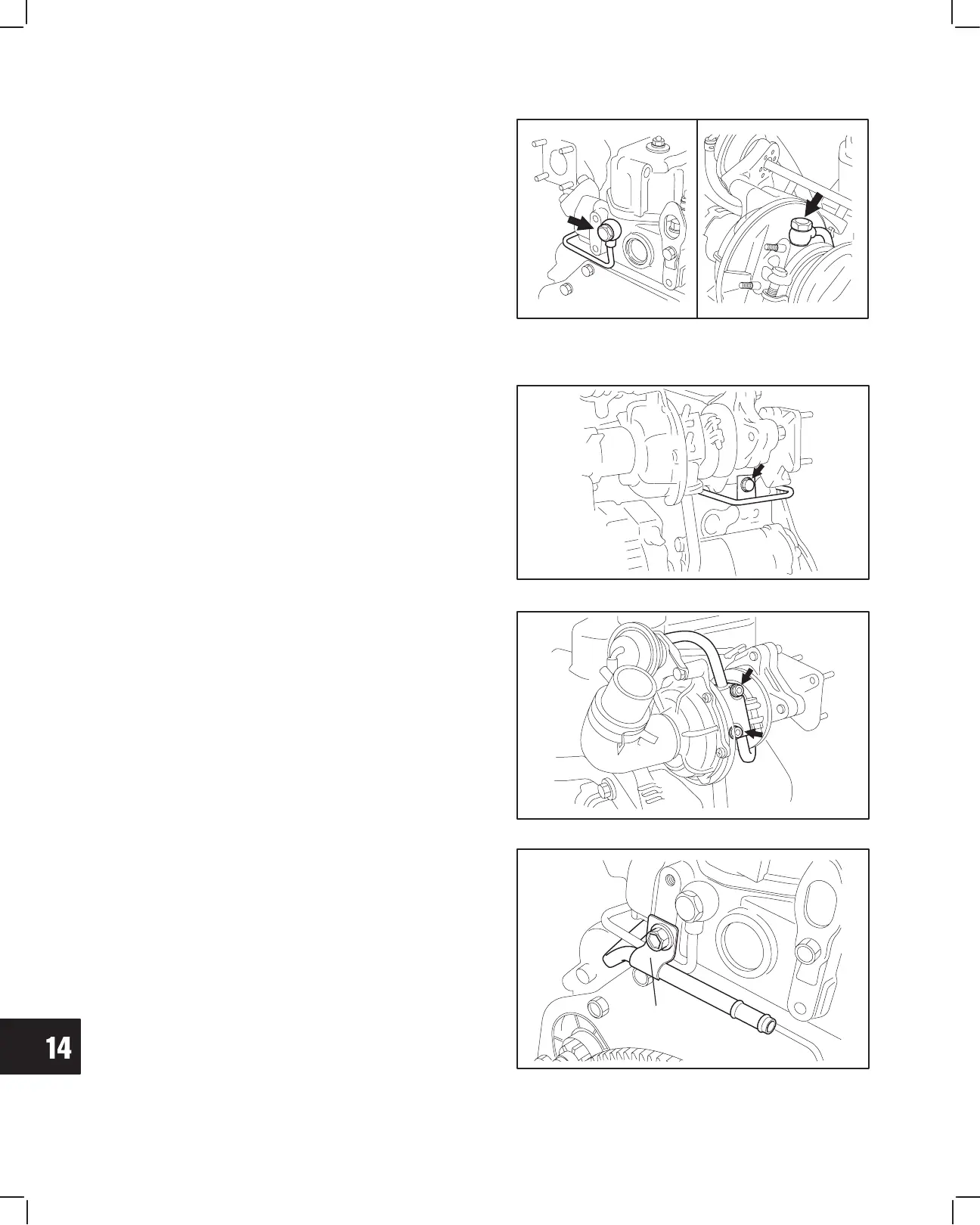
TURBOCHARGER
4. Install oil inlet line.
a. Temporarily install the union screw with
washers at the cylinder head.
b. Temporarily install the union screw with
washer at the turbocharger.
c. Temporarily install the inlet line bracket screw.
d. Then torque union screws and bracket screw.
Union screws:
Cylinder head side – Turbocharger side –
44.0 Nm 18.0 Nm (170 in-lb)
(32.0 ft.-lb)
Bracket screw:
19.0 Nm (170. in-lb)
Fig. 32 – Installing Oil Inlet Line
Fig. 33 – Installing Bracket Screw
5. Install Coolant Line at turbocharger with new
gasket.
a. Torque nuts to 8.0 Nm (70 in. lbs.).
Fig. 34 – Installing Coolant Line
6. Install bracket screw.
a. Torque screw to 19.0 Nm (170 in. lbs.).
TURBO WATER
PIPE CLAMP
Fig. 35 – Install Bracket Screw
 Loading...