11
5
GLOW PLUG SYSTEM
PREHEAT TIMER AND GLOW RELAY
The preheat timer and glow relay regulate current to
the glow plugs for preheating and starting. When the
keyswitch is turned to the “On” position, with the engine
cold, the preheat timer activates the glow plugs. An
indicator light lights and remains on while the glow
plugs are preheating the combustion chamber. When
the indicator light goes out, the engine may be started.
When the keyswitch is in the “Start” position, the glow
plugs and light are activated again as the engine is
cranking.
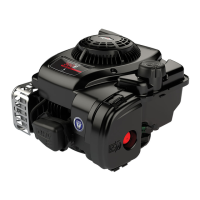
See Fig. 5 for terminal positions of the preheat timer
and glow relay.
Fig. 5 – Terminal Positions
PREHEAT TIMER
GLOW
RELAY
3
4
5
6
7
1
2
8
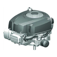
Testing Preheat Timer
The following test will be made with the meter in the
(DC Volts position), Fig. 6.
Turn keyswitch to “Off” position.
1. Insert BLACK meter test lead probe into terminal
#4.
2. Insert RED meter test lead probe into terminal #3.
3. Turn keyswitch to “On” position.
a. Glow light should light. Meter should display
1.5 volts maximum.
b. After 5 seconds (approximately), glow light
should go out. Meter should display approxi-
mately battery voltage.
4. Replace preheat timer if not to specification.
NOTE: If glow light does not light, replace bulb.
Fig. 6 – Testing Preheat Timer
3
4
1
2
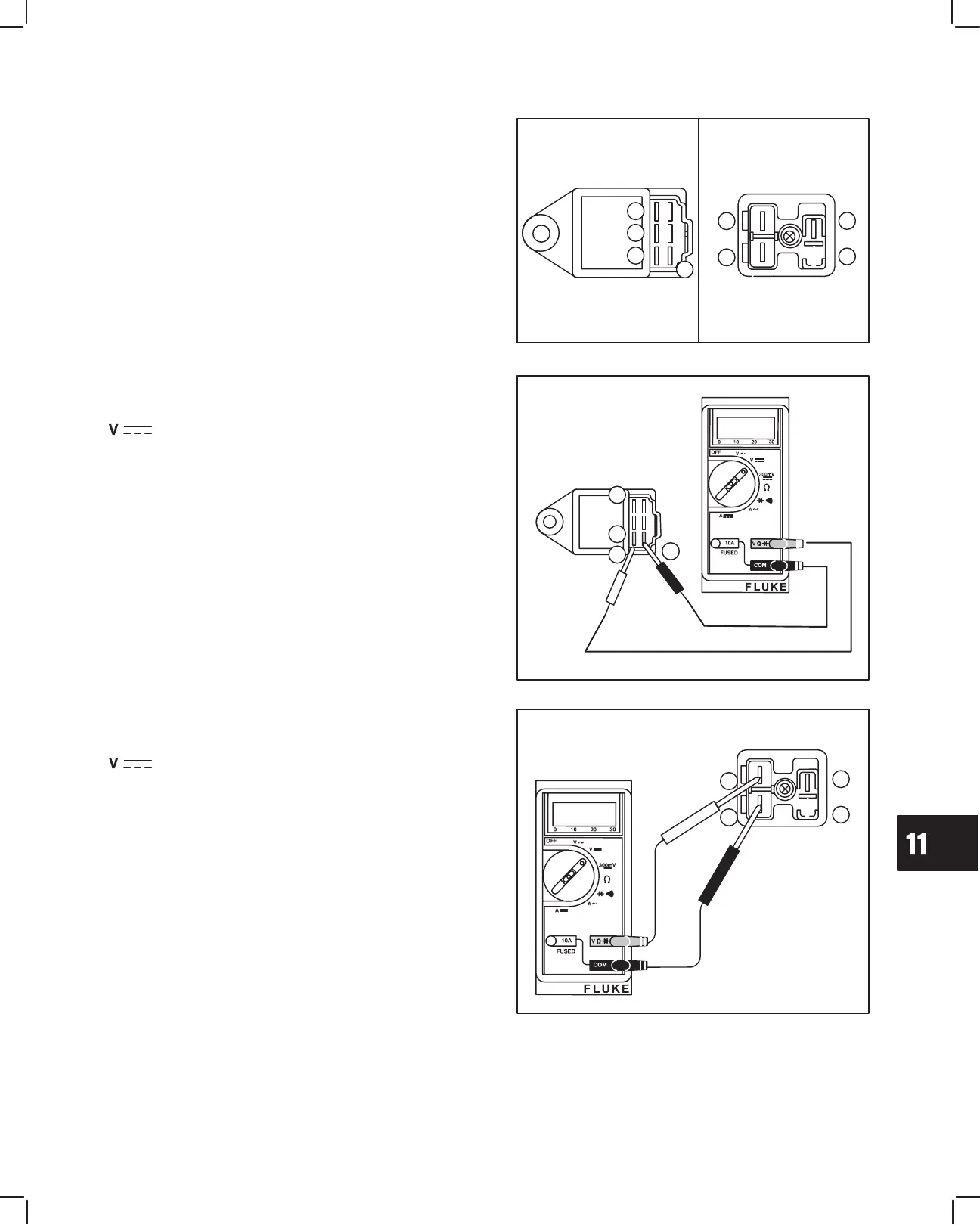
Testing Glow Relay
The following test will be made with the meter in the
(DC Volts position), Fig. 7.
Turn keyswitch to “Off” position.
1. Insert BLACK meter test lead probe into terminal
#8.
2. Insert RED meter test lead probe into terminal #7.
a. Meter should display battery voltage.
3. Turn keyswitch to “On” position.
a. Glow light should light. Meter should display
0.5 volts maximum.
b. After 5 seconds (approximately), glow light
should go out. Meter should display
approximate battery voltage.
4. Replace glow relay if not to specification.
Fig. 7 – Testing Glow Relay
5
6
7
8
 Loading...