11
21
STARTER SYSTEM
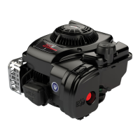
Check Pinion And Clutch Assembly
Check pinion and gear for damage, Fig. 56. Pinion and
shaft must rotate in clutch in clockwise direction only.
Bearings must turn freely.
NOTE: The pinion and clutch must be replaced as
an assembly.
Fig. 56 – Checking Pinion And Clutch
CLOCKWISE
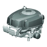
Assemble Pinion And Clutch Assembly
1. Lubricate the following components with silicone
grease before assembly, Fig. 57.
NOTE: See insert for correct assembly for type
starter.
a. Clutch gear.
b. Bearing retainer and roller bearings.
c. Drive gear.
d. Pinion shaft bearings.
e. Return spring ball.
f. Return spring.
Fig. 57 – Assembling Pinion And Clutch
E
F
D
A
B
C
D
1 KW
1.2 KW
1 KW
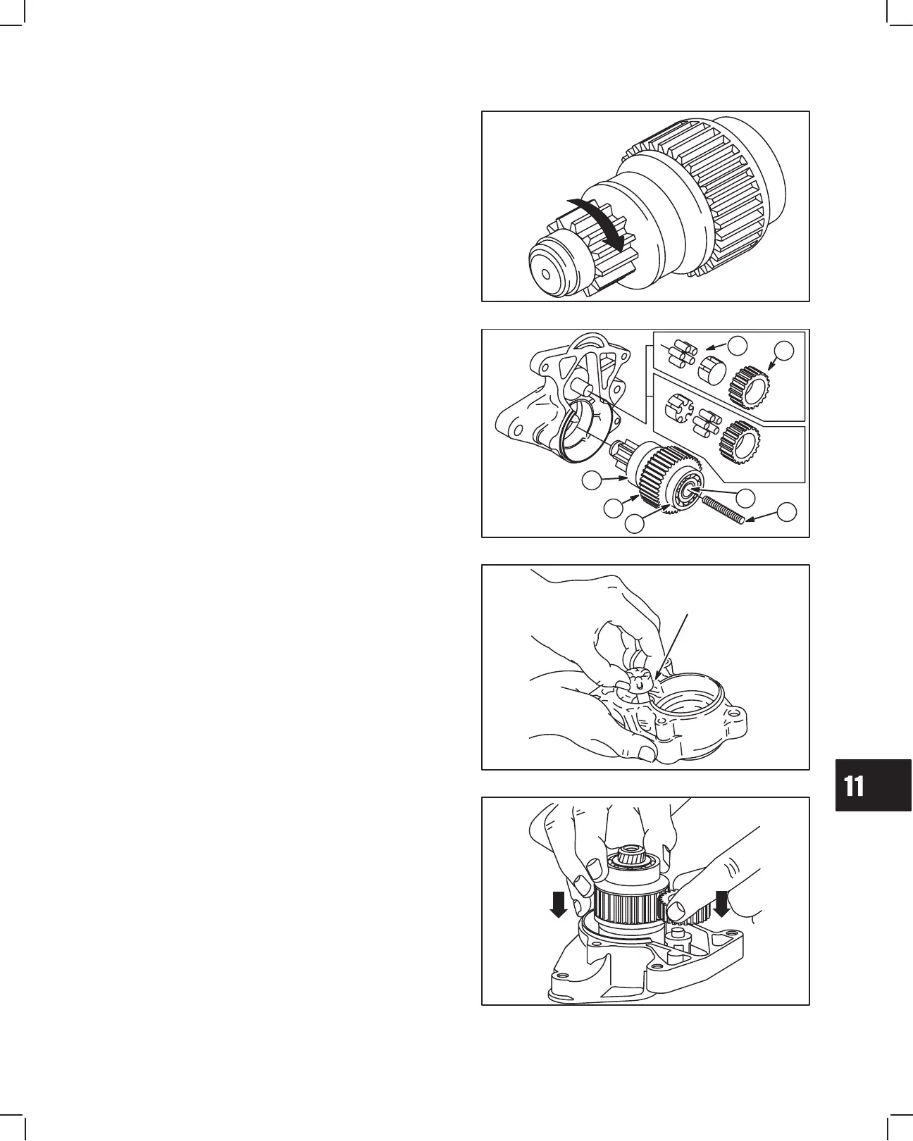
2. Assemble roller bearings and retainer to drive gear
shaft, Fig. 58.
NOTE: Roller bearings must face drive housing.
Retainer must face solenoid housing.
Fig. 58 – Assembling Roller Bearings
ROLLER BEARINGS
AND RETAINER
3. Mesh drive gear with clutch gear. Install pinion and
clutch assembly and drive gear into drive housing
together, Fig. 59. Install return spring ball in clutch.
Make sure roller bearings remain in position.
Fig. 59 – Assembling Drive Housing
 Loading...