2
11
CYLINDER HEAD AND VALVES
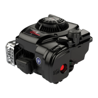
2. Install valve spring seats, Fig. 30.
NOTE: Lightly coat valve stems with Valve Guide
Lubricant #93963 before installing valves.
3. Install valves.
Fig. 30 – Install Valve Spring Seats And Valves
VALVE
SPRING
SEATS
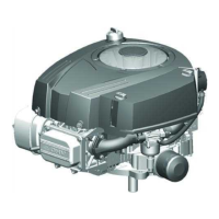
4. Install valve springs with valve spring compressor,
Tool #19417, Fig. 31.
NOTE: After installing valve spring retainer locks,
tap valve spring retainer lightly with a soft
hammer to ensure locks are seated.
Fig. 31 – Install Valve Springs
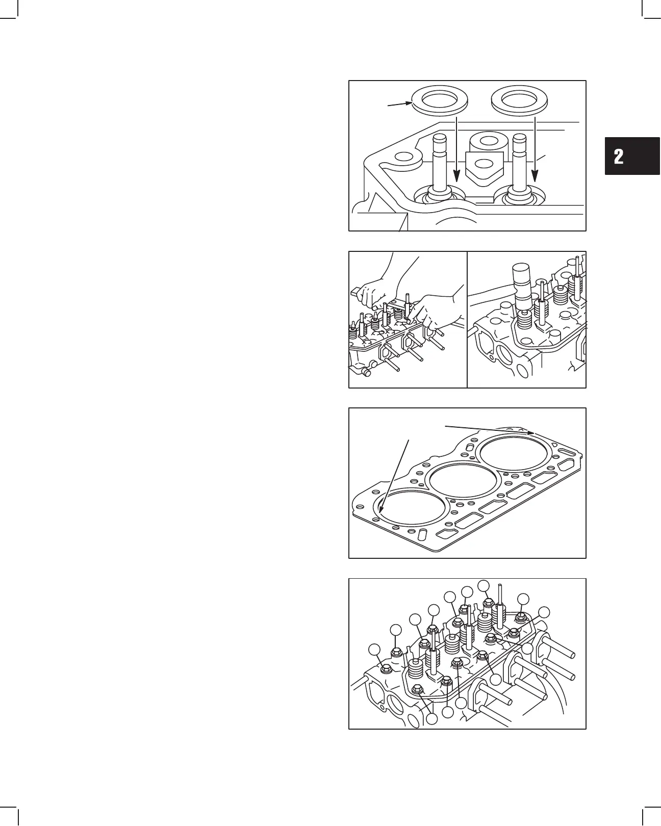
INSTALL CYLINDER HEAD
1. Place cylinder head gasket over alignment dowels
on cylinder block, Fig. 32.
NOTE: Make sure coolant, oil passages and head
bolt holes are aligned.
Fig. 32 – Install Cylinder Head Gasket
ALIGNMENT
DOWEL
LOCATIONS
2. Install cylinder head assembly, Fig. 33. Lubricate
threads of cylinder head bolts with engine oil.
Torque head bolts in 14.0 Nm (10 ft. lbs.) incre-
ments in sequence shown.
NOTE: Current style head bolts are 9 mm
diameter. Early style head bolts are 8 mm
diameter.
a. Torque 9 mm head bolts to 43.0 Nm (32 ft. lbs.).
b. Torque 8 mm head bolts to 34.0 Nm (25 ft. lbs.).
NOTE: Engine Models 58A447 588447 have 10
mm diameter head bolts. Torque head
bolts to 68 Nm (60 ft. lbs.).
Fig. 33 – Install Cylinder Head Assembly
3
4
5
6
7
1
2
8
12
11
10
9
14
13
 Loading...