3
5
TIMING GEARS AND GEAR CASE
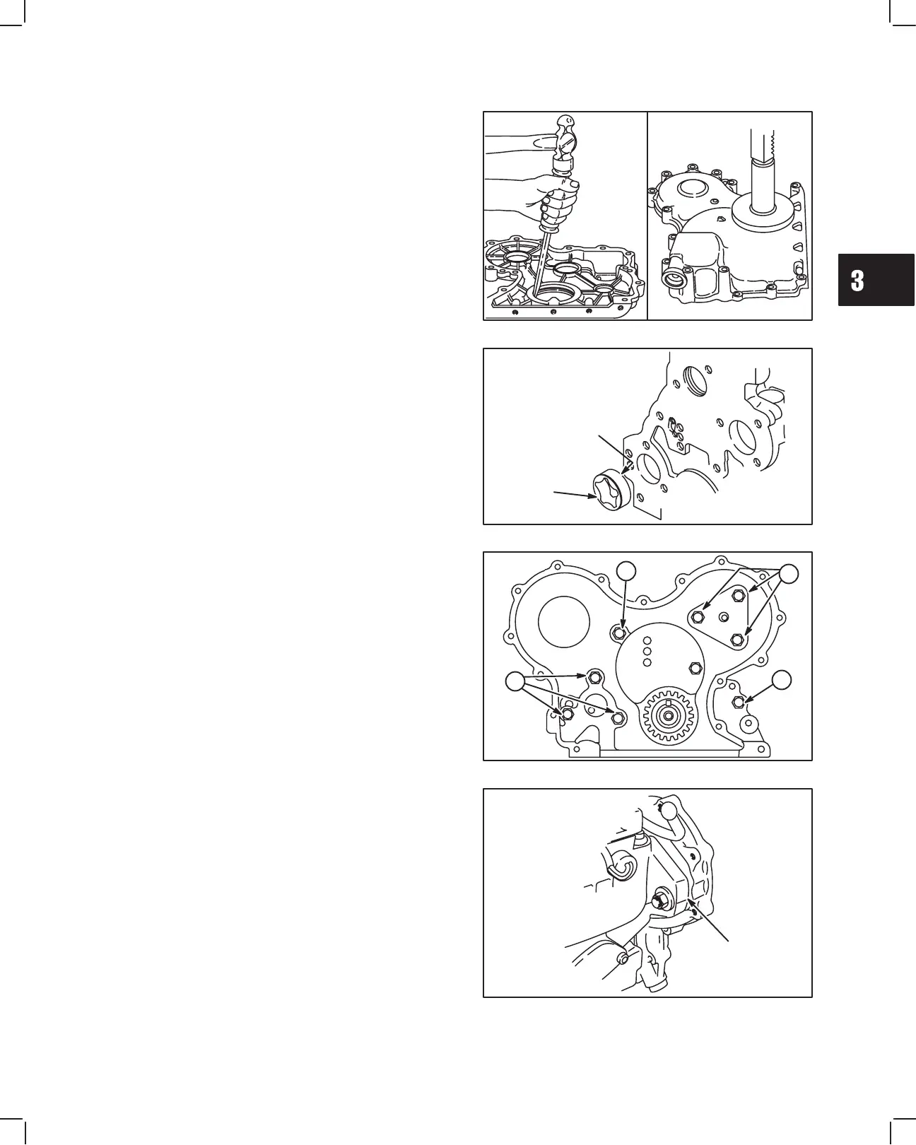
REPLACE TIMING GEAR COVER OIL SEAL
1. Drive out oil seal.
2. Use seal driver, Tool #19423, to install new oil seal,
Fig. 13.
Fig. 13 – Replacing Oil Seal
ASSEMBLE TIMING GEAR
CASE AND GEARS
1. Clean and lubricate oil pump rotor with engine oil
and install in cylinder block, Fig. 14.
a. ID mark on rotor must face cylinder block.
Fig. 14 – Installing Oil Pump Rotor
OIL PUMP
ROTOR
ID MARK
2. Install timing gear case with new gasket. Install
camshaft retainer, Fig. 15.
NOTE: It may be necessary to rotate oil pump
drive to engage oil pump rotors.
NOTE: Position camshaft retainer so that center
hole does not interfere with camshaft.
Note position, length and number of screws as shown.
a. M6 x 28 mm (M6 x 1.1”): 4
b. M6 x 18 mm (M6 x 0.7”): 3
c. M6 x 16 mm (M6 x 0.6”): 1
Torque screws to 8.0 Nm (70 in. lbs.).
Fig. 15 – Installing Timing Gear Case
B
A
C
A
3. Assemble injector pump to gear case with new
O-ring and install nuts and support bracket screw
finger tight, Fig. 16.
NOTE: Pump must be able to rotate.
a. Align timing mark on injector pump with timing
mark on gear case.
NOTE: See Section 10 for injector pump tim-
ing procedure.
Fig. 16 – Install Injector Pump
TIMING
MARKS
 Loading...