10
11
ENGINE SPEED
ADJUST IDLE SPEED
Engine should be at operating temperature before
adjusting idle speed.
Make sure speed control lever contacts idle speed
screw with engine at idle.
1. Loosen idle speed screw lock nut and adjust idle
speed screw to obtain RPM specified by model
and type number shown in chart, Fig. 23.
NOTE: Do exceed RPM shown for specific model
and type number.
a. Torque lock nut to 6.0 Nm (50 in. lbs.).
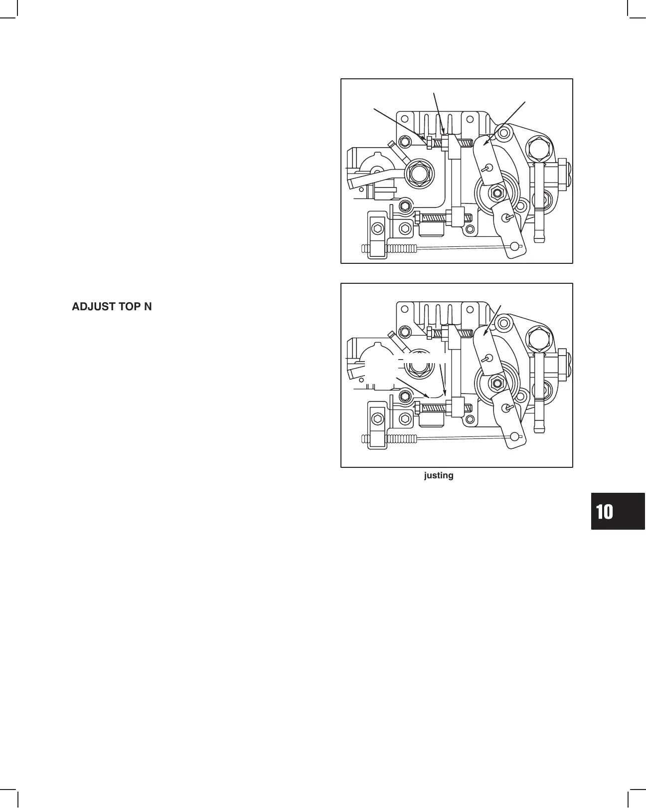
Fig. 23 – Adjusting Idle Speed
IDLE
SPEED
SCREW
SPEED
CONTROL
LEVER
LOCK NUT
ADJUST TOP NO LOAD SPEED
Engine should be at operating temperature before
adjusting idle speed.
Temporarily disconnect speed control wire at control
bracket on pump.
1. Remove and discard top no load wire and seal.
2. Loosen top no load speed screw lock nut.
3. Move speed control lever to FAST position and
adjust top no load speed screw to RPM specified
by model and type number shown in chart, Fig. 24.
NOTE: Do exceed RPM shown for specific model
and type number.
4. Stop engine and torque lock nut to 6.0 Nm
(50 in. lbs.).
5. Reassemble speed control wire at bracket.
a. Tighten screws securely.
b. Make sure speed control lever contacts top
no load screw when throttle lever is in
FAST position.
Fig. 24 – Adjusting Top No Load Speed
TOP NO
LOAD
SPEED
SCREW
SPEED
CONTROL
LEVER
LOCK NUT
 Loading...