2
9
CYLINDER HEAD AND VALVES
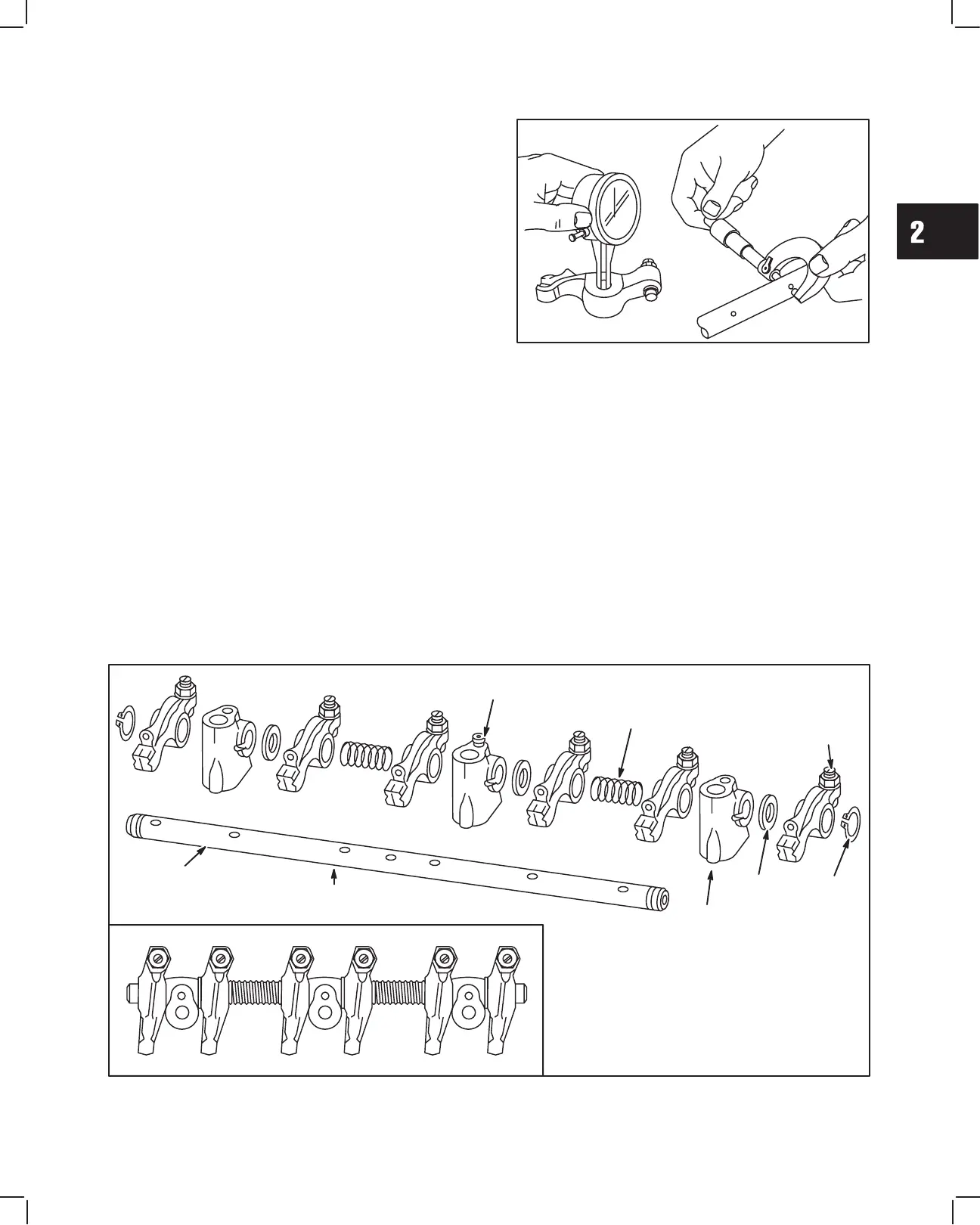
2. Check rocker arms and shaft, Fig. 26.
a. Check rocker arm-bearing surface.
Replace if greater than 10.03 mm (0.395 in.).
b. Check rocker arm shaft
Replace if less than 9.96 mm (0.392 in.).
c. Check rocker arm studs for stripped threads
and replace if required.
Fig. 26 – Checking Rocker Arm And Shaft
ASSEMBLE ROCKER ARM SHAFT
1. Oil all components before assembling. Small grooves in rocker shaft next to oil holes must face down. Assemble
rocker arm components, noting order of assembly as shown in Fig. 27. Note position of three thrust washers.
Install set screw in center rocker arm shaft support.
Fig. 27 – Rocker Arm Components
SET
SCREW
(1)
SPRING
(2)
ROCKER
ARM
(6)
SNAP
RING
(2)
THRUST
WASHER
(3)
ROCKER
ARM SUPPORT
(3)
ROCKER
ARM
SHAFT
OIL
GROOVES
DOWN
 Loading...