10
8
INJECTORS
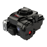
3. Check injector for leakage, Fig. 16.
Maintain injector pressure at approximately 120 Bar
(1707 psi), for about 10 seconds. Make sure there is no
leakage from nozzle or retaining nut area.
Fig. 16 – Checking Leakage
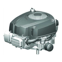
4. Check spray pattern of nozzle, Fig. 17.
Operate tester handle rapidly while observing pattern.
Spray pattern should be uniform and centered under
nozzle.
NOTE: A buzzing or chattering sound should also
occur while operating handle. Nozzle
should not drip between pump strokes.
Fig. 17 – Checking Spray Pattern
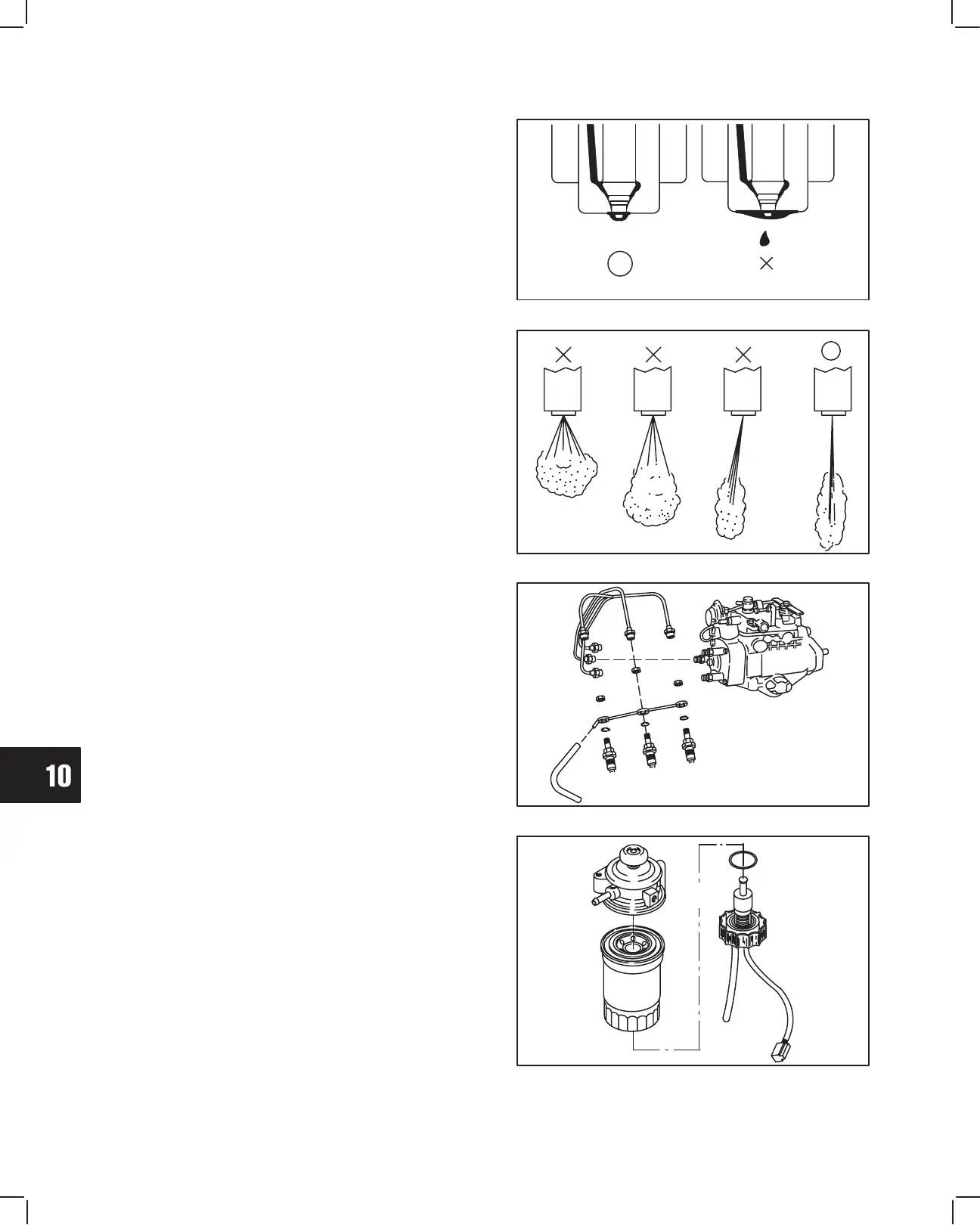
Install Injectors
Install injectors and fuel return line with new gaskets,
Fig. 18. Install fuel delivery lines.
a. Torque injectors to 61.0 Nm (45 ft. lbs.).
b. Torque fuel return line to 27.0 Nm (20 ft. lbs.).
c. Torque fuel delivery lines to 25.0 Nm
(220 in. lbs.).
Fig. 18 – Installing Injectors
FUEL FILTER – GENERAL
The fuel filter consists of a replaceable cartridge type
filter with a water level sensor and priming pump,
Fig. 19.
Replace fuel filter cartridge every 800 hours of engine
operation.
The water collector contains a float type sensor that
activates a warning lamp when it collects a minimum of
80 cc’s (2.5 fl. oz.) of water.
Fig. 19 – Fuel Filter
DRAIN PLUG
FILTER
O-RING
FLOATVENT PLUG
PRIMER
BUTTON
 Loading...